Dimensions and assembly, Electrical connection & configuration – Computronic Controls Sentinel 150P User Manual
Page 4
Sentinel 150P installation, operation & maintenance
ci0050 p4/8 issue 5 2014-08-26
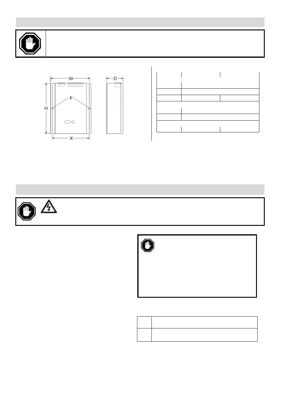
Dimensions and Assembly
CAUTION: Sentinel 150P chargers should be handled by the circuit board cover. Care should be taken not to
handle static sensitive components through exposed circuit boards and terminals.
SNTL150P
12V models
24V models
Overall:
W
108.6 mm / 4.28 in.
H
135 mm / 5.31 in.
D
45 mm / 1.77 in.
55 mm / 2.17 in.
Fixing holes:
X
99 mm / 3.90 in.
F
Ø 5.65 mm / 0.22 in.
Weight:
0.65 kg / 1.43 lb.
0.75 kg / 1.65 lb.
These chargers are designed for mounting in a vertical plane inside an enclosed control panel or housing.
Mounting orientation should be as shown above, with electrical connection terminals uppermost.
For safe heat dissipation, mount Sentinel in the orientation shown, with a minimum air-gap clearance of 40mm/1.5 in.
above/below and 25mm/1 in. at the sides. Consideration must be given to ventilation for proper heat dissipation.
For surface mounting, use the 2 centre fixing holes (Ø 5.65mm/0.22 in.). Ensure that the mounting studs/bolts/nuts/screws
adequately support the charger, and are tightened sufficiently to not to become loose during normal use, e.g. due to
engine/equipment vibration..
Electrical Connection & Configuration
DANGER !
HIGH VOLTS
WARNING: DANGER OF INJURY OR DEATH. During normal operation, Sentinel is
connected to high voltage AC circuits. Before connection, disconnection or handling of
these chargers, ensure isolation of all AC power supplies. Connection or disconnection with
live wiring can also cause hazardous sparking and component damage.
Connection terminals (general)
The Sentinel 150P uses a pair of two-part connectors with
removable screw terminal blocks:
CN1: a 7-way block for connection of the DC charge
output, temperature compensation remote sensor, relay
output and configurable input. Use a 5 mm/0.2 in. flat-
head screwdriver to tighten/loosen the terminals. For the
DC output, use 2.5mm/13AWG or larger connecting
wire.
CN3: a 3-way block for connection of the mains AC power
supply live, neutral and ground. Use a 5mm/0.2in flat-
head screwdriver to tighten/loosen the terminals.
For all AC supply/ground wiring, use 1mm/17AWG or
larger wire conductors rated for temperature 90°C/194°F.
For external fuse details, see the AC Input (power
supply) section following.
3 LEDs (coloured blue, green, red) provide indication of AC
supply, DC charge output and fault status.
For all models, wire connections for the DC charge output
(connector block CN1) and AC input supply (CN3) must be
physically separated, e.g. separate wire harnesses,
separately routed through the panels/ducting.
DC Charge Output
Before DC connection or disconnection:-
Ensure AC supply input is isolated.
Disconnecting the batteries while the
AC supply is live can result in sparking at
the battery terminals, ignition of battery
gasses and serious personal injury.
Check that the charger model and output
ratings are compatible with battery type &
voltage (see table below). Incompatibility
may result in damage to the charger,
batteries and serious personal injury.
Connect the Sentinel DC charge output to the battery terminals,
observing the warnings above and the correct
DC polarity:
CN1
pin
Function
1
2
+ DC charge output
– DC charge output
All SNTL150P models include an electronic, self-resetting DC
output fuse for protection of reverse polarity and short-circuit
faults. In the event of such faults, remove the cause of fault: the
charger will then attempt to automatically reset its fuse and re-
initialise the output. If the fuse fails to reset, contact your supplier
for further advice.