Electrical connection & configuration (cont.) – Computronic Controls Sentinel 150P User Manual
Page 6
Sentinel 150P installation, operation & maintenance
ci0050 p6/8 issue 5 2014-08-26
AC Input (power supply)
DANGER !
HIGH VOLTS
Before AC connection, disconnection or
fuse replacement:
Isolate the AC supply
Ensure a good ground/earth connection
to the charger (CN3 screw terminal).
Ensure the AC supply voltage is
compatible with the charger’s supply
rating. Exceeding the rated voltage
may result in damage to the charger
and connected equipment, and cause
serious personal injury.
Fit external supply fuses in accordance
with the charger's labelled types/ratings.
WARNING: Sentinel should be fused
separately from other equipment.
This will prevent Sentinel being isolated,
and ensure batteries remain on charge,
in the event that other equipment fails.
Connect the AC input supply (live, neutral and ground)
wires to Sentinel connector CN3:
CN3
pin
Function
1
2
3
AC supply live, 95 to 265 VAC, 47 to 63 Hz
AC supply neutral
AC supply ground/earth
AC supply and ground connections require 1mm²/17
AWG or larger wire conductors, rated for temperature
90°C/194°F. The AC live wiring must incorporate fuse
ratings/types as indicated on the charger labelling.
Sentinel
– PC connection
SNTL150P-PCCON configuration software kit
To allow the full range of programmable functions and
options, Sentinel must be connected to a Windows®-
based PC or laptop running Computronic SNTL150P-
PCSUITE software.
Configuration kit model SNTL150P-PCCON provides all
the necessary hardware for communication between PC
and Sentinel 150P charger.
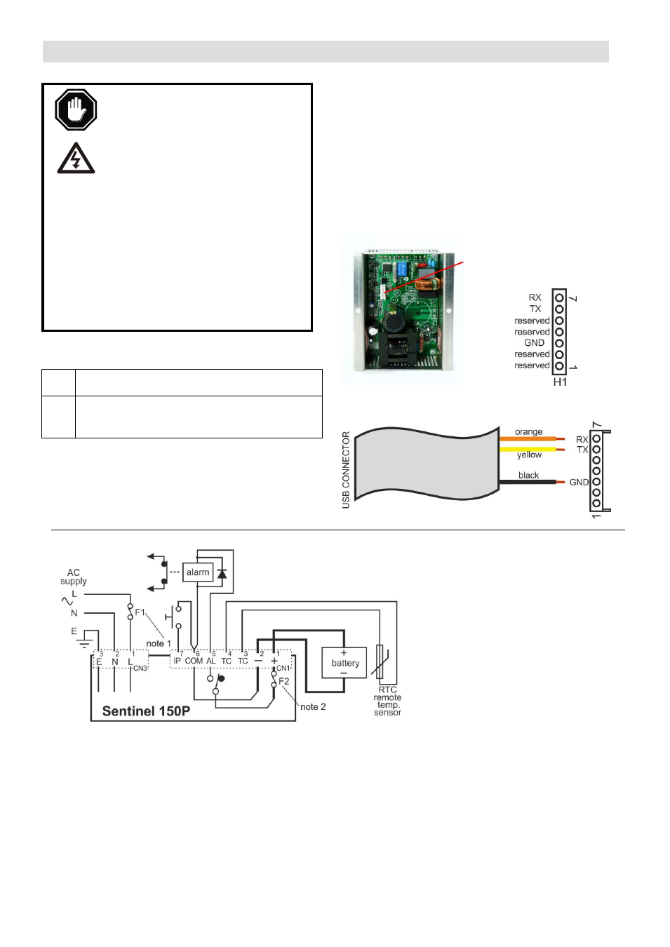
The kit includes a communication lead with a 7-way pin
header, which connects to the Sentinel 150P circuit
board. Sentinel back view:
7 way pin header H1
Connection:
Ensure correct polarity when mating with USB to
Serial TTL converter cable (as supplied with 42.70.3825):
Electrical Connection & Configuration (cont.)
Typical Connection
Notes:
1) External AC fusing (F1):
see AC Input (power supply) section
2) DC self-resetting fuse (F2):
see DC Output section
3) Battery output is isolated from chassis.
4) Alarm output relay shown in de-energised
state. Output function is configurable.
5) Input (pin 7) shown with momentary
action switch. Input function is software
configurable.