Phase out / discontinued check availability, General information (ctd), Sentinel current ratings – Computronic Controls Sentinel UL 70 User Manual
Page 4: Open frame models, Wall mounted enclosure models
Current Limiting
The Sentinel Battery Charger is current limited and will
only output the rated current of the charger (see chart
below)
MODEL
RATING
SNxUL70 & ESNxUL70
5A
SNxUL140 & ESNxUL140 12V
10A
SNxUL140 & ESNxUL140 24V
5A
SENTINEL CURRENT RATINGS
Battery Charged Condition
When charged the battery will only accept a charge to
replace the losses within the battery (approx. 1mA per AH of
battery). If there is a standing load (i.e. the panel controller
etc) the charger will output the standing load plus the losses
to the battery i.e. if a standing load of 1A is present with
50AH Vented Lead Acid batteries then charger will supply
1.05 amps.
A charged battery with open circuit terminals (i.e. no load
connected) will always be higher than nominal battery volt-
age (i.e. 12.6 on a 12V lead acid battery)
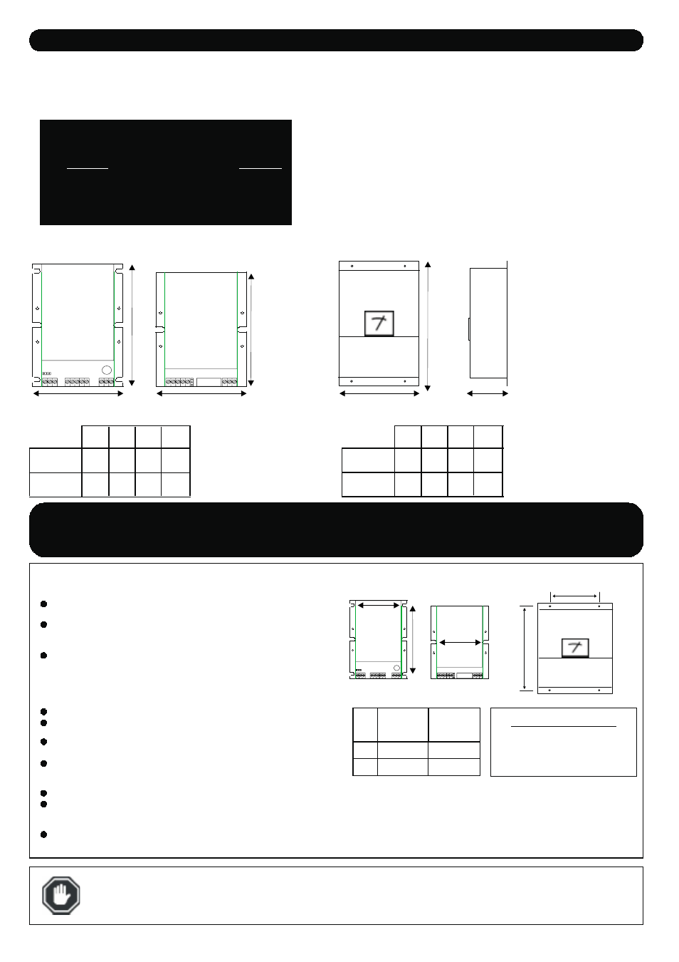
SNLUL
SNSUL
W
105mm
4.1”
105mm
4.1”
D
70mm
2.75”
70mm
2.75”
H
150mm
5.9”
130mm
5.1”
Weight
0.6Kg
1.3lbs
0.55Kg
1.2lbs
Dimensions
GENERAL INFORMATION (ctd)
Sentinel Installation Instructions - June 07 - Page 4 of 6
figure 1a - Open frame models
figure 1b - Wall mounted enclosed models
IMPORTANT ASSEMBLY INSTRUCTIONS -
SAVE THESE INSTRUCTIONS
OPEN FRAME MODELS -
SNSUL70, SNSUL140, SNLUL70 & SNLUL140
The charger must be mounted as shown in Figure 2a, with heatsink fins
in vertical position.
2 or 4 screws should be used to mount charger to panel. Ensure screws
are tightened firmly as as not to become loose during normal use on
engine.
Adequate consideration should be given to ventilation for proper heat
dissipation.
WALL MOUNTED ENCLOSURE MODELS -
The charger must be mounted as shown in Figure 2b.
By unscrewing the fixing screws the faces can be opened on their
hinges, to allow access to the internal connections.
Cable entry is via knock-outs on either side of the unit, these must be
must
carefully removed from the enclosure sides.
A suitable cable-gland (20mm/0.8” DIA) should be used to prevent
damage to cables and stop unwanted entry into inner part of charger.
See “Electrical Connection” for details of terminal connections.
The lower face should be firmly screwed to the charger before use.
Four screws should be used to mount charger to panel. Ensure screws
are tightened firmly as as not to become loose during normal use on
engine.
Adequate consideration should be given to ventilation for proper heat
dissipation.
Figure 2a -
open frame models
Figure 2b -
wall mounted enclosure models
CAUTION:
When handling chargers, care should be taken not to place excessive strain on either the heatsink, PCB,
transformer or connecting wires. Unit should be handled by main heatsink/case (open frame models) or steel enclosure
(enclosed models).
A
B
SNSUL
All models (mm)
95
SNLUL
All models (mm)
95
130
Fixing hole dimensions:
Width (between holes) - 66mm / 2.6”
Height (Between holes) -274mm / 10.75”
Fixing holes Ø=6mm (0.2”)
ESNSUL70, ESNSUL140, ESNLUL70 & ESNLUL140
SNSUL Range
SNLUL Range
SNSUL Range
A
A
B
WIDTH
WIDTH
HEIGHT
HEIGHT
SNLUL Range
ESNLUL
ESNSUL
D
115mm
4.5”
115mm
4.5”
W
140mm
5.5”
140mm
5.5”
H
281mm
11.1”
281mm
11.1”
Weight
1.6Kg
3.5lbs
1.6Kg
3.5lbs
Fixing Holes
Fixing
Holes
HEIGHT
WIDTH
DEPTH
PHASE
OUT
/ DISCONTINUED
Check
Availability