Phase out / discontinued check availability, Electrical connection – Computronic Controls Sentinel UL 70 User Manual
Page 5
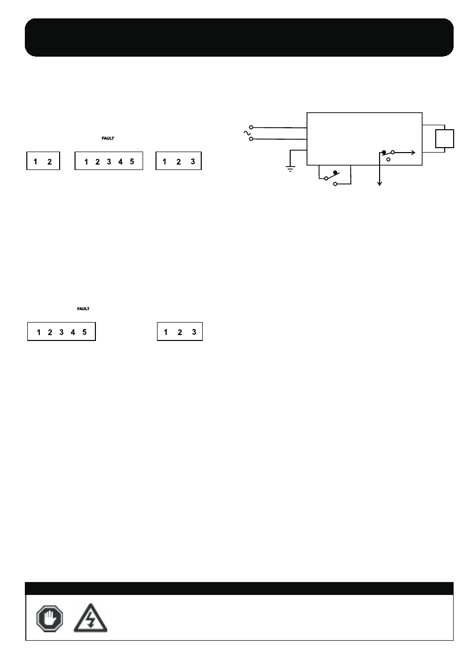
DC OUT
N/C
(To -Vdc)
N/C
(To -Vdc)
AC IN
GND
N
-Vdc
+Vdc
L
THERM
Connection to Mains Supply:
Ensure supply is isolated before connection is made to charging unit
Ensure unit is properly earthed at earth stud (enclosed) on chargers metal chassis
CAUTION: Ensure correct AC voltage is supplied to unit, applying 240VAC on a
120VAC unit will destroy it and could cause serious personal injury.
Connection to Batteries:
Ensure mains supply is isolated before connecting charger to batteries
Ensure battery type and voltage are correct before connecting to batteries
WARNING: Charging either different voltage or type of batteries from stated type
may result in damage to both the charging unit and/or batteries and
could result in serious personal injury.
Disconnection of Batteries:
Ensure mains supply is isolated before disconnecting charger from batteries
WARNING: Disconnecting the batteries whilst mains supply is connected to the
charger could result in a spark at battery terminals, this could ignite
the hydrogen given off from the batteries.
Boost Initiate Connection:
The charger will be in it’s normal mode of operation whilst the boost link is bro-
ken, upon connecting the two boost initiate terminals the charger will perform a
single auto-boost cycle, whereby the charger outputs a higher voltage, once bat-
tery voltage has reached this point, the charger returns to it’s normal float mode
of operation.
Over Voltage, Under Voltage and Charge Fail Connection (if fitted):
In a de-energised state the COM - N/C contact is alarmed. The relay energises
on power up and changes state. The contact is common to -Vdc and rated at 1A
@ 30VDC.
Fuses:
All Sentinel models are fitted with mains input fuses at the required ratings (see
markings on chargers). Before replacing any fuses, ensure charger is isolated
from mains supply.
Terminal Connection Information
Output:
DC Out (1 + 2) to battery
CAUTION: Observe correct polarity
Input:
AC supply
CAUTION: Observe correct voltage as stated on unit
ALARM INDICATION -
Over Voltage, Under Voltage and Charge Fail
3 - Change over contact for common alarm signal
(See notes on connection of alarms - see right)
Boost:
4 + 5 - Boost Initiate - Link these 2 connections to force
the charger from into a single boost cycle of operation.
(Once the charger has completed a single boost cycle
as outlined on page 3 of these instructions the charger
returns to it’s normal mode of operation)
IMPORTANT OPERATING INSTRUCTIONS -
SAVE THESE INSTRUCTIONS
Before operating the battery charger, ensure that the charger is assembled and installed as per the
section listed in these instructions.
The Sentinel Range are fitted with a self-resetting polyfuse on the dc output. If reverse polarity or short circuit faults are made, isolate supply, disconnect the
outputs and allow fuse to self-reset. The charger can then be re-connected and switched back on. No replacement of output fuse should be necessary.
If fuse fails to reset, the charger should be returned to supplier. Ensure correct rating when replacing input fuses.
AUTOMATIC BATTERY CHARGER
The Sentinel-L (SNL and ESNL) range are automatic battery chargers, if voltage falls below a preset voltage (12.2V on a 12V lead-acid battery) they
automatically enter an increased charging voltage state (boost). Once the batteries have reached this point, the charger will switch to it’s normal “float”
voltage. this prevents over-charge, which in turn prevents the battery from over-gassing and subsequently maximises battery life.
WARNING: DANGER OF INJURY OR DEATH.
Before connection, disconnection or handling
of SENTINEL battery charger, ensure that all AC power supplies are isolated. Connection to or discon -
nection from live wiring can also cause damage to internal components.
ELECTRICAL CONNECTION
WARNING:
The Sentinel range is not USER SERVICEABLE. No attempt should be made to replace or repair the charger, any attempt to do so may
invalidate any warranties and could cause serious personal harm or injury as well as damage to both the battery charger and any connected devices.
In event of failure the charger should be returned to supplier.
DC OUT
N/C
(To -Vdc)
N/C
(To -Vdc)
AC IN
GND
N
-Vdc
+Vdc
L
THERM
LINK FOR
BOOST
LINK FOR
BOOST
THERM:
monitoring remote battery temperature.
1 + 2 - Connect correct stated value of thermistor for
Output:
DC Out (1 + 2) to battery
CAUTION: Observe correct polarity
Input:
AC supply
CAUTION: Observe correct voltage as stated on unit
ALARM INDICATION -
Over Voltage, Under Voltage and Charge Fail
5 - Change over contact for common alarm signal
(See notes on connection of alarms - see right)
THERM:
monitoring remote battery temperature.
3 + 4 - Connect correct stated value of thermistor for
24V Models - 20K Thermistor
12V Models - 10K Thermistor
Thermistor Values
Sentinel Installation Instructions - June 07 - Page 5 of 6
SN UL70, SN UL140,
L
L
ESNLUL70, ESNLUL140
SNSUL70, SNSUL140, ESNSUL70, ESNSUL140
boost
boost
Battery
+
-
+
-
Alarm Contact
(Charge Fail, Under
and Over Volts)
AC
supply
PHASE
OUT
/ DISCONTINUED
Check
Availability