Wiring diagrams, Single channel dimming – CP Electronics VITM6-EBDSPIR-AD User Manual
Page 5
5
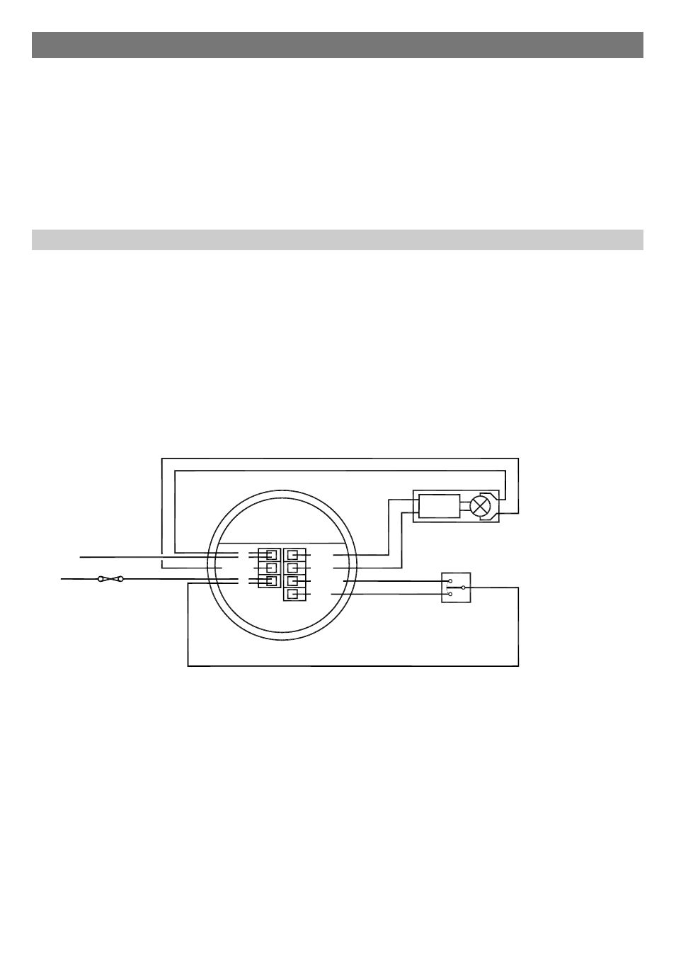
Single channel dimming
Wiring diagrams
Functions: Switches the luminaire with occupancy and maintains illuminance. Dims and switches using optional centre
biased retractive switch (MK K4900 or similar).
Configured to presence detection: Turns on automatically with occupancy. Maintains illuminance. Press and release
down switch to turn off. Press and release up switch to turn back on. Press and hold up switch to dim up, press and hold
down switch to dim down. Turns off after occupancy.
Configured to absence detection: Press and release up switch to turn on. Maintains illuminance. Press and release
down switch to turn off. Press and hold up switch to dim up, press and hold down switch to dim down. Turns off after
occupancy.
Channel mode: Set to “Switch and dim together”.
L/OUT
L
N
SW1/UP
+
-
SW2
DOWN
DIMMING
BALLAST
DIMMING LUMINAIRE
(1-10V)
CIRCUIT PROTECTION
(IF REQUIRED)
LIVE
NEUTRAL
CENTRE BIASED
RETRACTIVE SWITCH
(240V SWITCHING)
Optional for presence,
mandatory for absence detection
L/OUT
L
N
SW1/UP
SW2
DOWN
CIRCUIT PROTECTION
(IF REQUIRED)
LIVE
NEUTRAL
CENTRE BIASED
RETRACTIVE SWITCH
(240V SWITCHING)
Optional for presence,
mandatory for absence detection
LUMINAIRE
(NON-DIMMING)
+
-
Multiple luminaires may be connected in parallel to Channel 1 (via the N and L/Out terminals) as long as the maximum
total load is not exceeded.
Channel 2 (dimmable output) of the EBDSPIR-AD can be used to control the light output of luminaires that are fitted with
dimming ballasts/transformers.
The ballasts/transformers can be connected in parallel to Channel 2 (via the DIM– and DIM+ terminals). Refer to the
specification on page 12 for ballast quantities.
The wiring examples below show common methods of connecting the output channels for a single detector unit.