Advanced programming – CP Electronics VITM6-EBDSPIR-DD User Manual
Page 10
10
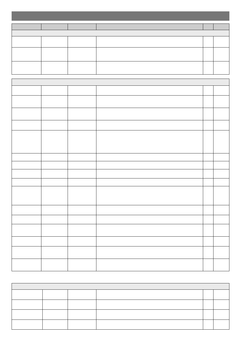
Parameter Name Default Value
Range / Options Description
UHS5 UNLCDHS
Channel 1 –Switching Channel
Detection Mode
Presence
Presence or
Absence
Presence mode allows the output to turn on when movement is detected and off
when movement ceases. Absence mode allows the output to turn off when
movement ceases, but must be manually turned on first.
Lux on level
(Switch level on)
9
1 to 9
For a higher resolution
a scale of 101-199 is
available
Sets a minimum light level below which the PIR sensor is enabled, allowing lights
to be turned on by movement.
Note: the Lux Level Off value must always be greater than the Lux Level On value.
Lux off level
(Switch level off)
9
1 to 9
For a higher resolution
a scale of 101-199 is
available
Sets a maximum light level above which the PIR sensor is disabled, preventing
lights from being turned on by movement.
Advanced programming
Switch Modes
2 position switch
together
Default
-
A single centre biased retractive switch will be used to control both channels
together.
2 position switch
separate
-
-
A single centre biased retractive switch will be used to control only the dimming
channel.
1 position switch
together
-
-
A single position retractive switch controls both channels together.
1 position switch
separate
-
-
Two single position retractive switches, controlling the channels separately.
Channel 2 -Dimming Channel
Detection Mode
Presence
Presence or
Absence
Presence mode allows the output to turn on when movement is detected and off
when movement ceases. Absence mode allows the output to turn off when
movement ceases, but must be manually turned on first.
Lux on level
(Switch level on)
9
1 to 9
For a higher resolution
a scale of 101-199 is
available
Sets a minimum light level below which the PIR sensor is enabled, allowing lights
to be turned on by movement.
Note: the Lux Level Off value must always be greater than the Lux Level On value.
Lux off level
(Switch level off)
9
1 to 9
For a higher resolution
a scale of 101-199 is
available
Sets a maximum light level above which the PIR sensor is disabled, preventing
lights from being turned on by movement.
Light Level
(maintained illuminance)
600
1 to 998 (999
disabled)
Sets a target light level to be maintained by the lighting system.
Load Type
DALI
DSI
DALI
DALI On
Sets the ballast control protocol to DSI.
Sets the ballast control protocol to DALI.
DALI On provides a permanent voltage to DALI ballasts when DALI has not been
implemented correctly in the ballast. Maximum number of ballasts is 5 unless the
relay is disabled then it is 10.
Max Value
100%
0 to 100%
Maximum dimming output level.
Min Value
0%
0 to 100%
Minimum dimming output level.
Memorise
N
Yes or No
If this is set to Yes, the last manual lux level set will be memorised and used as the
new switch on level.
On value
99
0 to 99
Dimming output level when switched on (0-99).
Off value
0
0 to 99
Dimming output level when switched off (0-99). If a non-zero off value is set, then
the output will toggle between this value and completely off depending on the
switch level on and off values. For example, if it is light outside, the fittings will be
off if there is no occupancy. If it is dark outside, they will adopt the preset off value.
This feature is only enabled if ‘Min value’ is set to 99.
Burn-in
0
0 (disabled) or
1 to 999 hours
Determines how long the output will be at 100% so that lamps ‘burn-in’. The ’burn-
in’ time is not affected by power supply interruptions.
Fade value
10
0 to 99
After occupancy ceases, this dimming output level is loaded for the fade time
(adjustable between 0 and 99).
Fade mins
0
0 to 99
This is the time period (adjustable between 0 and 99 minutes) that the luminaire
will be held at the fade value before turning off. A value of 0 disables the fade
function.
Speed On
40
Measured in 0.1
sec intervals.
Determines the dimming response speed after the setup time has finished.
Speed Set
5
Measured in 0.1
sec intervals.
Determines the dimming response speed during the set up time. Measured in 0.1
sec intervals. If set to 0 will disable dimming for “Set seconds” below, used if
fittings are required to warm up before dimming.
Set Seconds
120
1 to 999 seconds
Determines how long the dimming response set-up period lasts on power-up or on
setting change. This enables the desired lux level to be achieved rapidly when the
lights come on, or during setup.