S10 module terminals identification and marking – Crompton Controls 3DPM1CHS/10 User Manual
Page 4
Advertising
4
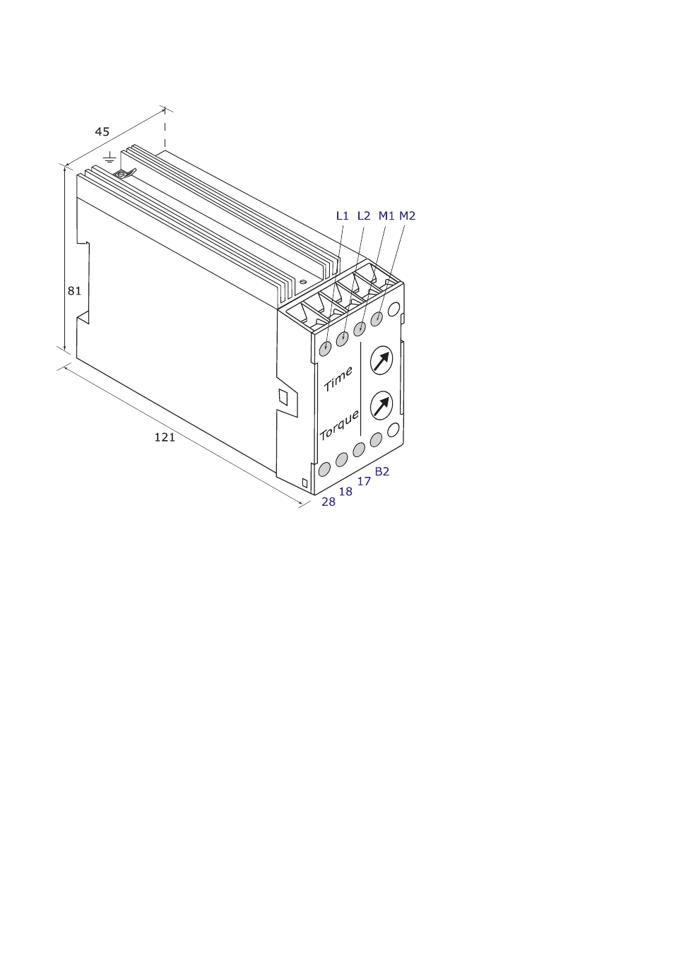
S10 Module Terminals Identification and marking
L1
Common phase connection
L2
Phase connection - connected to
M2
M1
Motor connection
M2
Motor connection - connected directly to
L2
B2
Voltage sense input
17
Relay input - common to RL1 and RL2
18
RL1 Relay output - motor contactor via stop start circuit
28
RL2 Relay output connects to brake contactor
The
B2
terminal to signal the unit to brake requires the full operating voltage of the
module applied.
L1
is common internally so a normally open auxiliary contact on the main contactor is
used to provide a signal on
B2
from
L2
.
Part Numbers
BR011 400v
BR016 240v
BR021 110v
Advertising
This manual is related to the following products: