Crompton Controls 3DPM1CHS/10 User Manual
Page 5
5
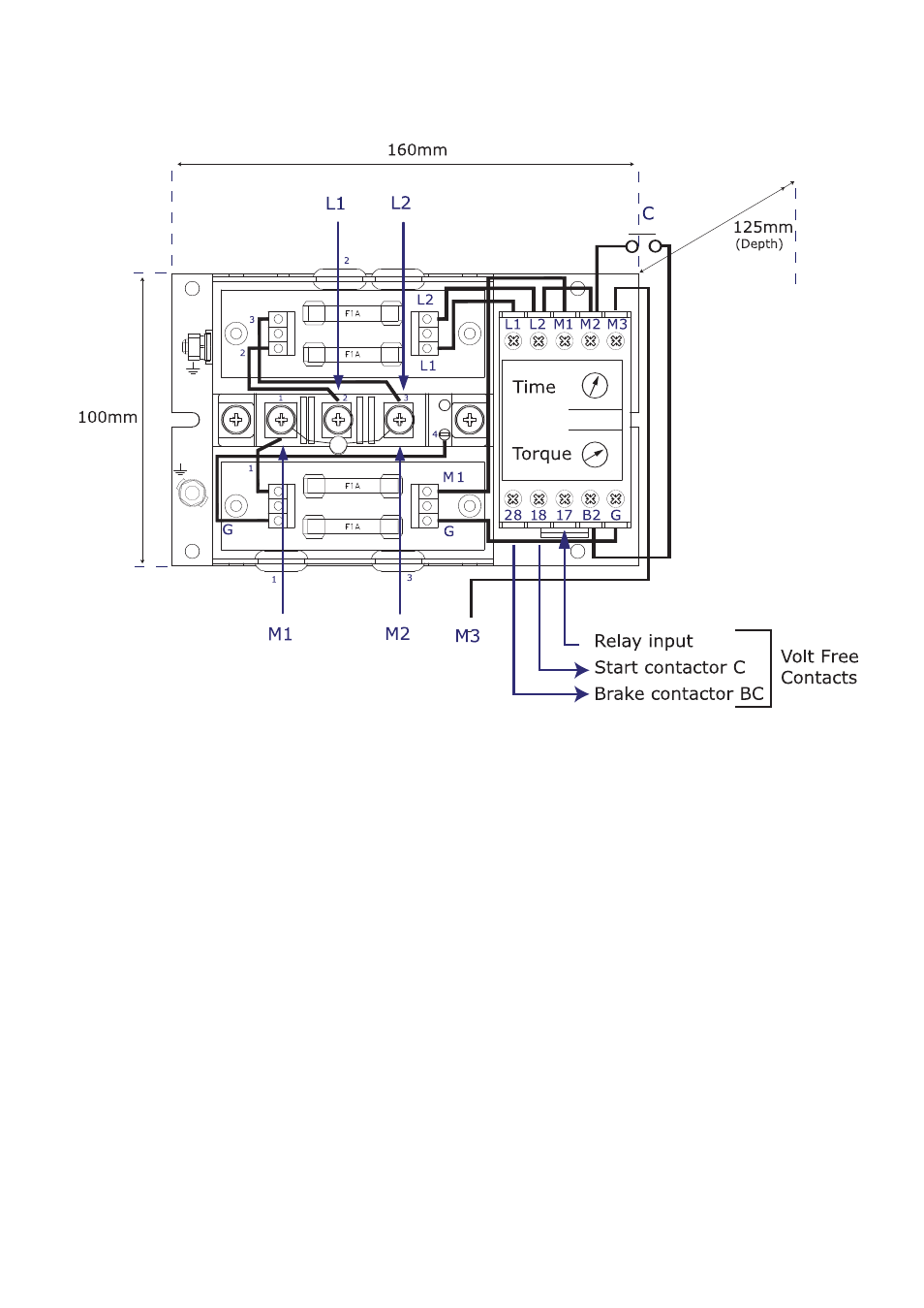
Smooth-BRAKE Module Terminals Identification and marking
Outline and Mounting Dimensions
Terminal Description
L1
Common phase connection to thyristor terminal 2
L2
Phase connection to thyristor terminal 3
M1
Motor connection to thyristor terminal 1
M2
Motor connection also to thyristor terminal 3
M3
Motor connection - generated voltage
B2
Voltage sense input relative to
L1
17
Relay input common to RL1 and RL2
18
RL1 Relay output - motor contactor via stop start circuit
28
RL2 Relay output connects to brake contactor
G
Gate to connect to external thyristor
NOTE:
A Voltage Dependant Resistor – VDR is fitted across the
M1 M2
motor terminals
to protect the diode.
Terminal covers not shown - MUST be fitted.
PCB fuse rating - 500V, 1A, quick blow, 6.3mm x 32mm ceramic tube, eg SIBA
ref: 70-065-63 1 Amp or equivalent.
Part Numbers
BR025 400v 60A
BR026 400v 90A