Pl - plasma lift – Future Automation PL User Manual
Page 7
In
st
all
at
io
n
: S
ta
ge
2
Page 6 of 20 // email [email protected] tel: +44 (0) 1438 833577 fax: +44 (0) 1438 833565
PL - Plasma Lift
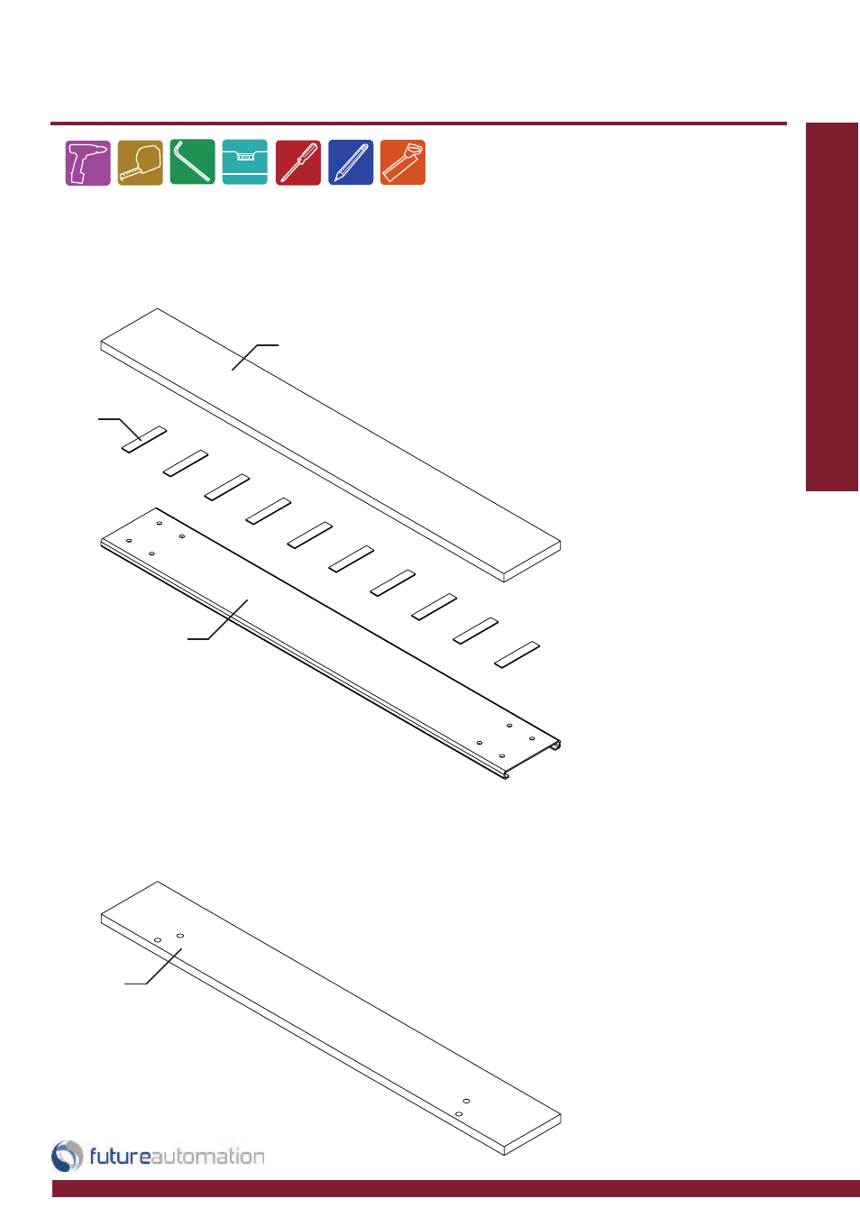
Fitting Flap Panel to the Mechanism
The 6mm flap and the base should be made as part of the cabinet.
The surfaces of the flap should ideally be varnished or painted to help prevent it from warping.
Take care when fixing the
surfaces together. Place the
objects on a flat surface to
make sure the edges are
properly alligned when they
come into contact.
Try to use as many self
adhesive pads as possible to
get the most secure fixture.
4 holes to be drilled in base panel.
These holes should be12mm diameter
to allow for adjustment later.
Use frame as a template to mark hole
locations.
Example hole locations shown above
are for the Group A frame.
Bolt through the support frame
then through base panel into the
black plates on the beam using
M8 x 30mm or M8 x 35mm bolts
Make sure the base panel lines
up squarely, directly on top of the
lifting beam.
Consult PL TECHNICAL SHEET
before fabricating any flaps or
base panels.
Base
Aluminium Flap
Adhesive
Pad
Flap
Screw base in place from
underside through the 2 fix-
ing brackets on either side.