Product diagram, Hardware connections – Holland Electronics HMDD-1U User Manual
Page 4
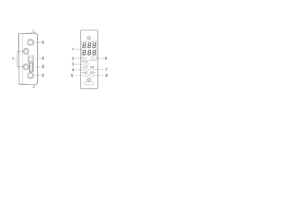
5. PRODUCT DIAGRAM
1 Audio Left & Right Output,
RCA connector
2 Video Output , F connector
3 Service connector
4 Power connector
5 Off-air antenna input,
F connector
1 Message and Channel Display
3 CH+ Button search channel up
4 CH- Button search channel down
5 Zoom button select screen format 4:3/16:9
letterbox, full, zoom or center.
7 SCAN Button searches for off-air ATSC signals
8 Audio button selects Audio Language (SAP)
2 LOCK LED indicate signal/channel locked
6 IR receiver (Not Functional)
REAR PANEL
FRONT PANEL
-3-
6. HARDWARE CONNECTIONS
a. The HMDD is designed for installation in a chassis designed for mini demodulators.
Mini demodulator chassis such as the HOLLAND HMR can be mounted in
b. The HOLLAND HMR 12-unit rack chassis and HOLLAND HMPS power supply should
standard 19” EIA racks.
be used with the HMDD. Up to 11 HMDDs can be configured into a HOLLAND
HMR with the HOLLAND HMR stabilizer bar in place or 12 HMDDs
with the stabilizer bar removed.
c. When configuring the HMDD in the chassis with the power supply it is critical that
the power harness being used is from the same vendor as the power supply,
and is designed for that specific supply. Power supply harnesses among
vendors are not interchangeable and can severely damage the HMDD.
d. The use of a surge protector and a UPS is highly recommended.
Product warranty does not cover surge or spike damages.
e. Connect a 75-ohm coaxial cable with proper connectors from the HMDD
Antenna Input Port to an Off-Air antenna .
f. For mono audio output connect an audio patch cable with RCA male
connectors on both ends between the HMDD Audio LEFT (White) output port
to the modulator’s audio input. For output to a stereo modulator use patch cables
from the HMDD Audio LEFT (White) and RIGHT (Red) output ports.
g. Connect a coaxial cable using a male F-connector to the HMDD Video
Output and a male F-connector to the modulator’s video input
h. Note you will require 1 HMDD for each channel or subcarrier to be converted
and demodulated. You will also require 1 modulator for each channel to be
remodulated.
i. Connect the HMDD to the power harness and power supply installed in the
mini demodulator chassis.
-4-