The following table defines the response d format – Holland Electronics NE 1101L User Manual
Page 18
- 18 -
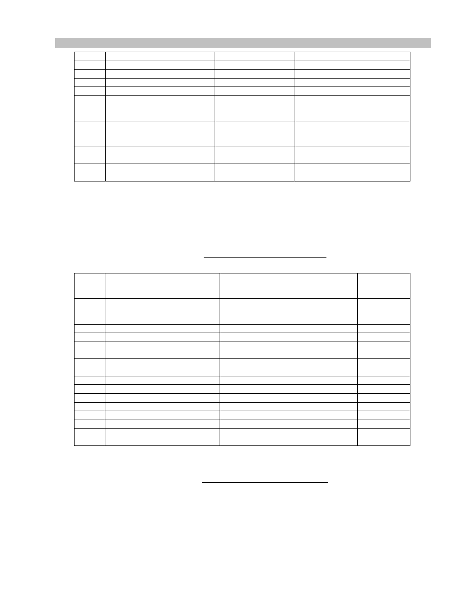
Forward Optical Receiver
Operation Manual
5
12V CURRENT
255 = 10A
Range: 0 – 255
6
24V CURRENT
255 = 10A
Range: 0 – 255
7
24V DC
102 = 24V
Range: 0 – 255
8
12V DC
102 = 12 V
Range: 0 – 255
9
5V DC
102 = 5 V
Range: 0 – 255
10
Firmware version, major
Binary (0-255)
Major revision number
(equivalent to the first digit in
display format)
11
Firmware version, minor
Binary (0-255)
Minor revision number
(equivalent to the last two digits in
display format)
12–
17
(reserved)
18 <C1>
Trailing
Marker
(C1 in Hexadecimal)
TABLE 4: Response to Command B
The following table defines the response D format.
Byte
#
Description
Bit Definition
(note)
Remark
0 <C0>
Leading
Marker, in
hexadecimal
1
Channel A Optical Level status
B0: Loss channel A optical level alarm
2
Channel B Optical Level status
B0: Loss channel A optical level alarm
3
RF level Status
B0: Loss RF signal alarm
4
Pilot Tone Status
B0: Loss Pilot alarm
5
24V DC Supply Status
B0: 24V DC Voltage alarm
6
12V DC Supply Status
B0:12V DC Voltage alarm
7
5V DC Supply Status
B0: 5V DC Voltage alarm
8
CURRENT (24V)
B0: 24V Current alarm
9
CURRENT (12V)
B0: 12V Current alarm
10-17 (reserved)
18 <C1>
Trailing
Marker,
in hexadecimal
Note: 1. B0 = bit 0 (the LSB), B1 = bit 1, B2 = bit 2
2. Bit set = alarm, bit clear = no alarm
TABLE 5: Response for Command C