Fixture linking, Data cabling, Dmx data cable – ILUMINARC Ilumipanel™ 28 IP User Manual
Page 10: Signal distribution, Ixture, Inking, Abling, Etup
6
Ilumipanel 28 IP Optic RGB User Manual (Rev. 6)
3.
S
ETUP
Fixture Linking
You will need a serial data link to run light shows of one or more fixtures using a DMX-512 controller
or to run synchronized shows on two or more fixtures. The combined number of channels required by
all the fixtures on a serial data link determines the number of fixtures the data link can support.
Important:
Fixtures on a serial data link must be daisy chained in one single line. To comply with the EIA-
485 standard no more than 32 devices should be connected on one data link. Connecting more
than 32 fixtures on one serial data link without the use of a DMX optically-isolated splitter may
result in deterioration of the digital DMX signal.
Note!:
USITT recommends limiting the total length of the DMX cable (from the first fixture/controller to
the last fixture) to 300 ~ 455 m (985 ~ 1,500 ft). The maximum recommended number of fixtures
on a serial data link is 32 fixtures.
Data Cabling
To link fixtures together you must obtain data cables. If you choose to create your own cable please
use data-grade cables that can carry a high quality signal and are less prone to electromagnetic
interference.
DMX Data Cable
Use a Belden© 9841 or equivalent cable which meets the specifications for EIA RS-485 applications.
Standard microphone cables cannot transmit DMX data reliably over long distances. The cable will
have the following characteristics:
2-conductor twisted pair plus a shield
Maximum capacitance between conductors – 30 pF/ft.
Maximum capacitance between conductor and shield – 55 pF/ft.
Maximum resistance of 20 ohms / 1000 ft.
Nominal impedance 100 – 140 ohms
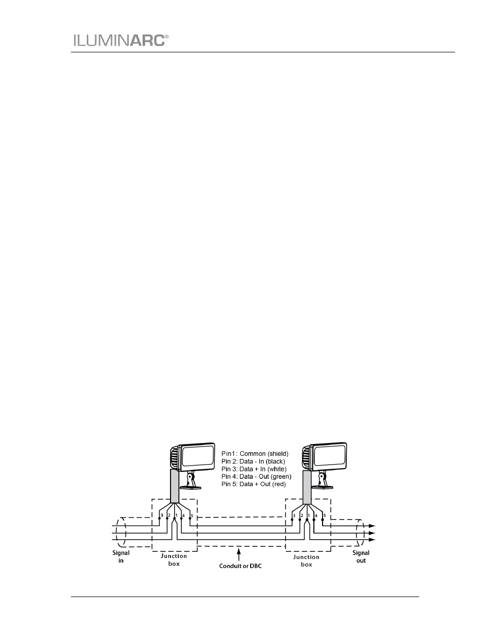
Signal Distribution
Connect the bare-ended signal cable from the product to a signal distribution box as indicated below.