Successful power up, Front panel – Ivie iFlex 2400 Series User Manual
Page 3
i
FlexHardware Manual
Ivie Technologies, Inc.
After checking cable integrity, and if the modules and controls are all programmed, any
module can be plugged into any slot - the iFlex 2400 will find it and properly identify it.
The same thing is true of the RJ-45 logic I/O ports. The “smart” remote controls, IR
sensors etc. can be plugged into any I/O port.
The identity chips in the remote controls and IR sensors will tell the iFlex what the
connected device is and the Sonata software will provide positive indication that a
device is connected and operational. Phantom Power has been activated where necessary
and nominal levels have been preprogrammed such that the system will essentially be
“plug-and-play.”
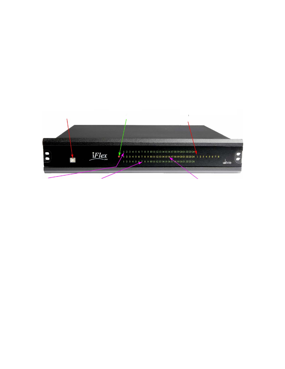
Channel Input (green).
Dual Function Indicator (green). 1) Channel Output:
Channel Active (yellow).
Lights when an input card
Lights when an output card is plugged into the
Lights when signal is
is plugged into the channel. channel. 2) Gating Indicator: If an input card is
present in the channel.
plugged into the channel, light indicates “gated on.”
Figure 1
Successful Power Up
The PCM50US24 universal power supply is used with the iFlex and provides a broad
mains voltage operating range: 100 to 240 VAC, 47 - 63 Hz. Successful powering of the
iFlex can be verified by the lighting of the power indicator LED. When first powered on,
the iFlex initiates a self test which checks a number of their operating parameters to
verify proper performance. The flashing
LED’s on I/O cards give positive indication that
the self test cycle is underway.
Front Panel
The front panel of the iFlex houses a USB port and 81 indicator lights. The USB
connector is used to communicate with the iFlex using the Sonata software and a
computer via USB connection. The indicator lights illuminate to show power, inputs,
outputs, gating, channel active and malfunction status. Figure 1 illustrates the front panel
indicator lights and their functions:
Fault Indicators (yellow,1 - 8).
Light only when there is a fault
and provide fault code.
USB Conmmunications Port
“Power” Indicator.