Knox Video ProSwitch User Manual
Page 3
KNOX VIDEO
ProSwitch ROUTING SWITCHERS
KNOX VIDEO
ProSwitch ROUTING SWITCHERS
Page 4
Page 3
Connect one or two audio destination devices (amplifiers, VCRs, tape/CD
recorders, RF modulators, etc) to the left and right channel RCA or Phoenix
connectors marked AUDIO OUTPUT. Devices may be terminated with a 1Kohm
load for unbalanced destinations, or 600 ohms for balanced destinations.
Do not connect a SOURCE of audio to any of the audio OUTPUT connectors.
For balanced audio units, the Phoenix connectors may be removed while
making the screw connections.
When installing balanced audio connections, use the center pin for the
common or ground wire. The top or bottom pin may be used for either + or -,
however, the connections must be consistent throughout.
2.6 RS232 CONNECTION
The ProSwitch can be controlled through its RS232 port. To use an external
controller, connect a source of RS232 data to the 9-pin connector on the rear of the
unit. The ProSwitch is wired as a data terminal; that is, data in goes to pin 3, data
out from pin 2, and pin 5 is common (ground). A direct connection from a PC
compatible usually works well; select 9600 baud, 8 bits, no parity, and 1 or 2 stop
bits.
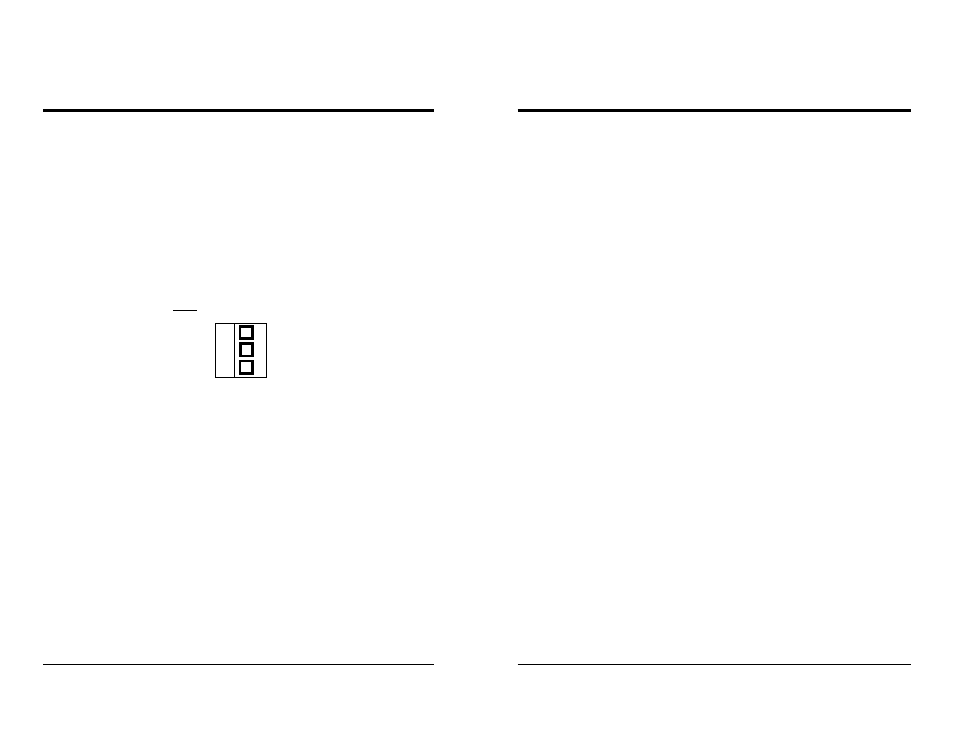
C
Phoenix connector
for Balanced
Audio
SECTION 3. OPERATION
3.1 INTRODUCTION
This section explains in detail the operation of the ProSwitch using either the
front panel pushbutton switches or the RS232 port.
3.2 CONNECTIONS
Connect audio and video sources as described in sections 2.4 and 2.5. There is
no requirement that all inputs be used or terminated, but be sure that all outputs are
terminated.
An output may be looped back to an unused input via short cables for the
purpose of adding a delay, but be aware that if an output is then routed to that
same input an illegal condition will exist and the output will oscillate at
frequencies which could spill over onto other crosspoints.
3.3 ROUTING VIA THE FRONT PANEL SWITCHES
On powerup, input source number 1 is always connected to output destina-
tions number 1 and number 2.
Select the output destinations (VIDEO1 and/or AUDIO1, VIDEO2 and/or
AUDIO2) you wish to route to and push the corresponding front panel button(s).
If routing both audio and video push both buttons down at once. The LEDs above
the buttons you have selected will light. Then select the input source number you
wish to route from and push that button.
To route a different input to the output(s) already selected, just push another
input button number. To select a different output destination to be routed to, push
and hold one or more output buttons--the LEDs will change to your new selection.
If you wish to route audio and video to both outputs simultaneously, hold all
four buttons down; all four LEDs will light.