Knox Video RS16x16HB User Manual
Page 4
KNOX VIDEO
RS16x16HB ROUTING SWITCHER
KNOX VIDEO
RS16x16HB ROUTING SWITCHER
Page 3
Page 4
SECTION 2. INSTALLATION
WARNING!
Static Sensitive Connectors! During the installation process and whenever
changing cables to the Knox RS16x16HB inputs and outputs, use extreme caution
to avoid conducting static electricity to any inputs or outputs including video,
audio, and RS232.
DC Offset Warning! Connect standard video and audio inputs and outputs only.
Do not connect input or output signals with a positive or negative dc offset.
Chassis Ground is Earth Ground Do not connect video or audio cables with
induced or direct-connection potential on the shield.
2.1 INTRODUCTION
This section provides the information required for installation of the RS16x16HB
into its operating environment.
2.2 UNPACKING AND INSPECTION
Unpack the RS16x16HB carefully and verify that the serial number matches the
number quoted on the packing list. Before installing it into a system, check the
outside of the unit carefully for signs of damage and check that none of the fasteners
have come loose.
Check that the power module is also present and marked for use with the
RS16x16HB product.
Units are shipped with a memory backup battery which retains the routing
crosspoint information when power is off. The battery is mounted on the printed
circuit board and is accessible from the rear panel. In the event that crosspoint
information is not retained during power off, the battery must be replaced. It is
recommended that the battery be replaced after five years. See Section 4,
Maintenance, for details on how to change the battery.
2.3 INSTALLATION
The RS16x16HB is designed to be mounted in a standard 19” rack panel; it is
10.5 inches, or six standard units, high.
Choose a space in the rack which is convenient for all the cables and mount the
unit using standard rack bolts. Connect the output of the RS16x16HB power unit to
the power connector at the right rear (as viewed from the back of the panel) of the
RS16x16HB and plug the power unit into a grounded AC power outlet of the voltage
and frequency specified on the power unit. There is no power switch on the
RS16x16HB; it is designed to be ON at all times. (If it is desirable to have the
RS16x16HB powered down regularly, connect the power module to a switchable
AC power strip.)
2.4 VIDEO CONNECTIONS
Connect up to sixteen video sources (cameras, videocassette players, RF
demodulators, still-stores, character/graphics generators, etc.) to the input BNC
connectors marked VIDEO INPUT (or RCA connectors, if they were specified).
Inputs are automatically terminated in 75 ohms. Terminate unused outputs in
75 ohms.
Connect up to sixteen destination devices (monitors, VCRs, LCD projectors,
displays, RF modulators, etc.) to the sixteen BNC (or RCA) connectors marked
VIDEO OUTPUT. Be sure that all destination devices are terminated at 75 ohms.
Do not connect a SOURCE of video to any of the video OUTPUT connectors.
2.5 AUDIO CONNECTIONS
Connect up to sixteen audio sources (line level mikes, videocassette players, RF
demodulators, tape/CD players, etc.) to the left and right channel connectors marked
AUDIO INPUT.
Connect up to sixteen audio destination devices (amplifiers, VCRs, tape/CD
recorders, RF modulators, etc.) to the sixteen left and right channel connectors
marked AUDIO OUTPUT.
Do not connect a SOURCE of audio to any of the audio OUTPUT connectors.
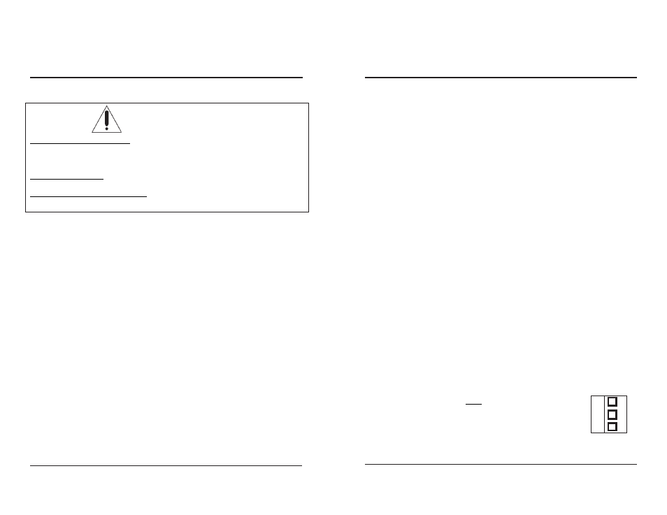
For balanced audio units, the Phoenix connectors may be removed while
making the screw connections.
When installing balanced audio connections, use the center pin for the common
or ground wire. The top or bottom pin may be used for either +
or-, however the connections must be consistent throughout.
C
Phoenix connector
for Balanced
Audio