Knox Video RS8x8HB User Manual
Page 9
KNOX VIDEO
RS8x8HB ROUTING SWITCHER
KNOX VIDEO
RS8x8HB ROUTING SWITCHER
Page 13
Page 14
SECTION 4. MAINTENANCE
NOTE: Maintenance of the RS8X8HB, except for changing the battery, should
be performed by qualified service people only.
4.1 INTRODUCTION
The only routine maintenance the RS8x8HB requires is to change the battery
located at the rear of the RS8x8HB unit.
4.2 HOW TO CHANGE THE MEMORY BACKUP BATTERY
The RS8x8HB is shipped with a memory backup battery which retains the
routing crosspoint information when power is off. The battery, approximately 1/2
inch in diameter, is mounted in a holder on the main printed circuit board. In the
event that crosspoint information is not retained during power off, the battery must
be replaced.
To change the battery pry up the retaining bar gently and slip the old battery
out. Replace at least every five years with Knox part number 140896, or commercial
type DL1220.
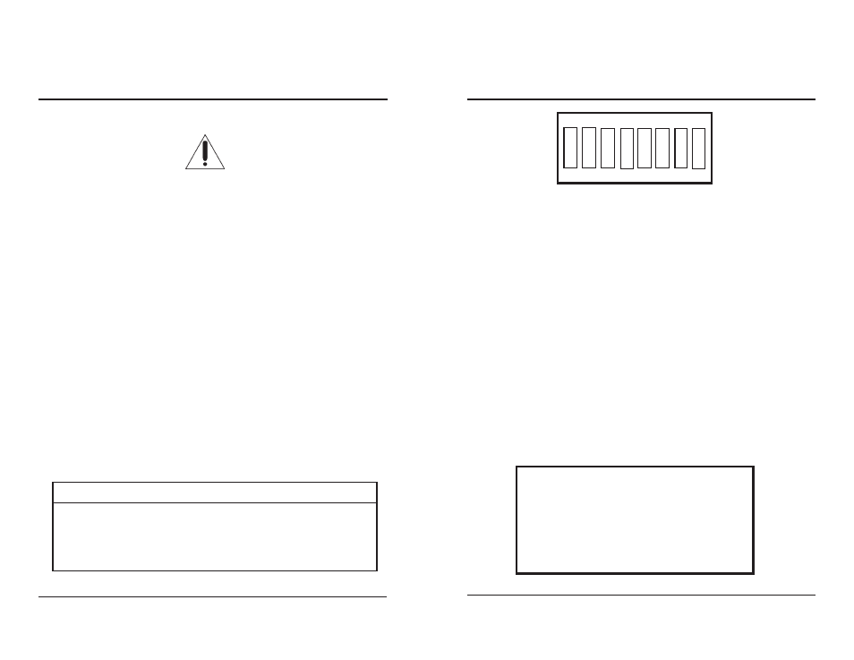
4.3 SETTING THE BAUD RATE
An 8-position switch, accessible through the rear panel, is provided for setting
the baud rate and certain programming functions. Switch positions 1 and 2 are used
to set the baud rate for the RS232 control port. One of four baud rates may be
selected as follows:
BAUD RATE
19200
1200
2400
9600
SWITCH 1
ON
OFF
ON
OFF
SWITCH 2
ON
ON
OFF
OFF
4.4 SETTING THE ANSWERBACK MODE
The user may choose between two modes of answerback: verbose and non-
verbose. Select the mode using position 3 of the programming switch located on
the rear panel of the RS8x8HB. Position 3 ON is verbose, while position 3 OFF is
non-verbose.
In the verbose mode, each time a routing command is sent, the current routing
map will be reported on the RS232 line followed by the word DONE.
The switches are read by the microprocessor only at power-up; for switch
configuration changes to take effect, cycle the power input to the RS8x8HB.
OUTPUT 1
Video 3
Audio 1
OUTPUT 2
Video 2
Audio 2
OUTPUT 3
Video 1
Audio 3
OUTPUT 4
Video 6
Audio 6
OUTPUT 5
Video 7
Audio 7
OUTPUT 6
Video 8
Audio 8
OUTPUT 7
Video 5
Audio 1
OUTPUT 8
Video 4
Audio 1
1
ON
2
3
4
5
6
7
8
Figure 4.1 Baud Rate Setting
Figure 4.2 Typical Routing Map Status Report
Switch position 3 chooses between the verbose and non-verbose mode of
operation (see section 2.7). Position 3 ON is verbose, while position 3 OFF is non-
verbose.
Switch position 4 is used to disable the timed sequencer (see section 3.3.4).
Position 4 ON disables the timed sequencer.
Switch position 5 is used to disable the breakaway audio feature (see section
2.9). Position 5 ON disables the breakaway audio feature.
Switch positions 6 through 8 are reserved for programming options not covered
here. Switches 6 through 8 should always be OFF.