Chipset – NEXCOM NISE 2100 User Manual
Page 76
Copyright © 2011 NEXCOM International Co., Ltd. All Rights Reserved.
63
Chapter 4: BIOS Setup
NISE 2100, NISE 2100A, NISE 2110, NISE 2110A User Manual
Chipset
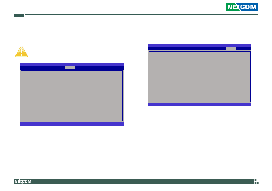
This section is used to configure the system based on the specific features
of the chipset.
Setting incorrect field values may cause the system to malfunc-
tion.
BIOS SETUP UTILITY
v02.61 (C)Copyright 1985-2006, American Megatrends, Inc.
← →
Select Screen
↑↓
Select Item
Enter Go to Sub Screen
F1
General Help
F10 Save and Exit
ESC Exit
Configure North Bridge
features.
Advanced Chipset Settings
WARNING: Setting wrong values in below sections
may cause system to malfunction.
u
North Bridge Configuration
u
South Bridge Configuration
North Bridge Configuration
This section is used to configure the north bridge features.
BIOS SETUP UTILITY
v02.61 (C)Copyright 1985-2006, American Megatrends, Inc.
← →
Select Screen
↑↓
Select Item
+-
Change Option
F1
General Help
F10 Save and Exit
ESC Exit
North Bridge Chipset Configuration
PCI MMIO Allocation: 4GB to 3072MB
Initiate Graphic Adapter
[IGD]
Internal Graphics Mode Select
[Enabled, 8MB]
DVMT Mode Select
[DVMT Mode]
DVMT/FIXED Memory
[256MB]
Boot Display Device
[CRT + LVDS]
Flat Panel Type
[1024x768 18bit]
Initiate Graphic Adapter
Selects the graphics controller to use as the primary boot device.
Internal Graphics Mode Select
Selects the amount of system memory used by the internal graphics de-
vice.
Select which graphics
controller to use as the
primary boot device.
Chipset
Exit
Security
Advanced
Boot
Chipset
PCIPnP
Main