OT Systems FT040DB User Manual
Page 12
FT040DB Series Installation & Operation Manual
12
Dip switch settings for various types of data transmissions
Function / Switch No.
Sw. 3
Sw. 4
RS485 (2-Wire)
OFF
OFF
RS422/485 (4-Wire)*
OFF
ON
RS232
ON
OFF
* Factory setting [RS422/485 (4-Wire)]
Dip switch settings for line terminations
Line Output Termination
Line Input Termination
Function / Switch No.
Sw. 1
Line Output Terminated
ON
Line Output Unterminated*
OFF
Function / Switch No.
Sw. 2
Line Input Terminated
ON
Line Input Unterminated*
OFF
* Factory setting (Line Output and
Line Input “Unterminated”)
Industrial practice for line terminations
For RS422 4-wire communication, it is suggested to keep the input and output lines
terminated in the ONE Tx to ONE Rx configuration.
For RS485 2/4-wire communication, the RS485 device can be disabled to stay in a Hi-Z
state. It is very important that the data lines have to be terminated with a resistor being
connected across the pair wires so as to eliminate the residual standing signal waves on the
lines in the Hi-Z line condition. So, it is recommended that the lines should be terminated with the
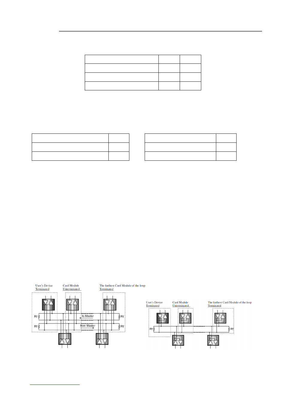
appropriate resistance. When more than one RS485 device are connected in a daisy-chain
configuration, only the farthest device on the loop, i.e. the device located at the end of the line,
should be terminated; whereas the middles ones are set to “Unterminated” status. See the figure
4.6 below for reference.
(a) RS485/422 4-wires Bus structure
(b) RS485 2-wire Bus structure
Fig. 4.6 Termination of different Bus structures