Rcm-4 connections, Controller input rmx control port – Oxmoor RCM-4 User Manual
Page 10
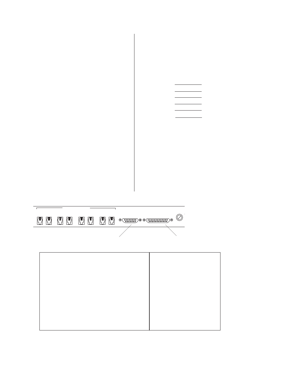
RMX CONTROL PORT
FUSE
CHANNEL D
CONTROLLER
INPUT
CHANNEL C
CHANNEL B
CHANNEL A
IN
OUT
IN
OUT
IN
OUT
IN
OUT
REMOTE CONTROLS
1
6
1
6
1
6
1
6
1
6
1
6
1
6
1
6
RCM-4 CONNECTIONS
Page 8
(Please refer to Figure 7.0)
CONTROLLER INPUT
Female, 15-pin, standard D-sub connector.
Pin # Pin Assignment
1 ....................... Common
2 ....................... Common
3 ....................... Source Select Option
4 ....................... A + B Combine
5 ....................... B + C Combine
6 ....................... C + D Combine
7 ....................... D + A Combine
8 ....................... + 5 VDC@ 225mA
(same as pin 15)
9 ....................... Common
10 ..................... Common
11 ..................... A Source Select
12 ..................... B Source Select
13 ..................... C Source Select
14 ..................... D Source Select
15 ..................... + 5 VDC @ 225mA
(same as pin 8)
REMOTE CONTROLS
Channels A through D, female 6-pin TELCO
connectors.
IN
OUT
Pin #
Pin #
1
6
2
5
3
4
4
3
5
2
6
1
Pin # Shunted to Common
Action
PIN # Forced to Common
CONTROLLER INPUT
RMX CONTROL PORT
(WITH SOURCE SELECT OPTION TIED TO COMMON)
3 ................................. Source Select Option
12, 7, 22, 17
4 ................................. A + B Combine
12, 7, 22, 17, 8, 11
5 ................................. B + C Combine
12, 7, 22, 17, 6, 23
6 ................................. C + D Combine
12, 7, 22, 17, 18, 21
7 ................................. D + A Combine
12, 7, 22, 17, 9, 20
4 & 5 ........................... A + B + C Combine
12, 7, 22, 17, 8, 11, 6, 23, 24, 10
5 & 6 ........................... B + C + D Combine
12, 7, 22, 17, 6, 23,18, 21, 19, 5
6 & 7 ........................... C + D + A Combine
12, 7, 22, 17, 18, 21, 9, 20, 24, 10
7 & 4 ........................... D + A + B Combine
12, 7, 22, 17, 9, 20, 8, 11, 19, 5
* .................................. A + B + C + D Combine
12, 7, 22, 17, 8, 11, 6, 23, 24, 10,
18, 21, 20, 9, 19, 5
*
Any three of pins 4 through 7.
RMX CONTROL PORT
Female, 25-pin, standard D-sub connector.
Low-voltage
DC:
Pins 8 and 15 of the RMX
Controller Port are identical, paralleled DC
outputs providing +5 VDC at 225 mA
maximum. This supply may be utilized to
power LED indicators, etc.
Figure 7.0: Example Of Interaction Between The RCM-4 Controller Input and RMX Control Port