Rcm-4 callouts – Oxmoor RCM-4 User Manual
Page 4
RCM-4 CALLOUTS
Page 2
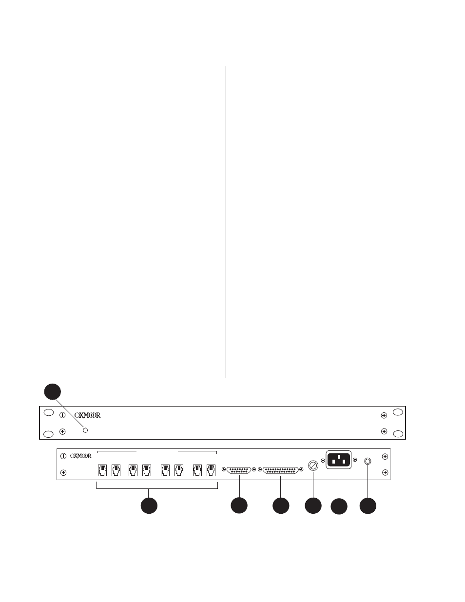
Figure 1.0: Front and Rear Panel Views of RCM-4
(Callouts refer to Figures 1 and 2)
1. POWER LED
- The front panel LED is illuminated
when the unit is on. The absence of an On/Off
switch is a performance safety feature, eliminat-
ing accidental shutdown during operation.
2. REMOTE CONTROLS
- Female 6-pin modular
TELCO connectors. Channels are paralleled
when a combine command is given through the
CONTROLLER INPUT. While this may facili-
tate a variety of custom remote switching func-
tions, it is primarily designed for linking
Oxmoor's RC-16 and RC-2 Remote Volume
Controls.
3. INTERNAL RELAY
- Links the Remote Control
channels A, B, C, and D of the RCM-4 (i.e.: A to
B, B to C, C to D, D to A) when a combine com-
mand is given through the CONTROLLER IN-
PUT.
4. MOMENTARY PULSE
- When a zone combine
command is given through the CONTROLLER
INPUT, causing some remote controls to be-
come linked, Pin 1 on the IN connector and Pin 6
on the OUT connector of each affected REMOTE
CONTROL line are momentarily shorted to
common. This is intended to be used with
Oxmoor's DCA-2 Digital Control Attenuator.
When the DCA-2 sees this momentary pulse it
will force all affected audio channels to a prede-
termined volume level.
5. CONTROLLER INPUT
- Female, 15-pin, standard
D-sub connector. The CONTROLLER INPUT
provides access to RCM-4 control functions. Ap-
plication of a latching type contact closure be-
tween the controller input pins and common
causes pre determined combinations of the
modular Telco connectors to be connected in
parallel. DC power of +5VDC @225mA is pro-
vided for powering LEDs, etc.
6. RMX CONTROL PORT
- Female, 25-pin, standard
D-sub connector. This port provides control of
the Oxmoor RMX Mixing Matrix Products. Sig-
nals issued via the CONTROLLER INPUT
cause contact closures to occur between appro-
priate CONTROL PORT pins and common. The
RMX Mixing Matrix uses these signals to com-
bine certain audio channels.
7. FUSE HOLDER
- Replace only with approved
type of fuse in a rating appropriate to the mains
voltage, as indicated on back panel. (see SPECI-
FICATIONS).
8. POWER CONNECTOR
- Standard IEC 3-pin con-
nector for AC power cord. Use only with
grounded (3-wire) outlets. Cord sets are avail-
able for all world connection standards.
9. CHASSIS GROUND POST
- Nuts on a threaded
stud conveniently enable the installer to secure
the chassis to the sound system ground.
RMX CONTROL PORT
FUSE
POWER
CHASSIS
SERIAL NUMBER
CHANNEL D
CONTROLLER
INPUT
CHANNEL C
CHANNEL B
CHANNEL A
IN
OUT
IN
OUT
IN
OUT
IN
OUT
REMOTE CONTROLS
1
6
1
6
1
6
1
6
1
6
1
6
1
6
1
6
RCM-4
POWER
RCM-4 ROOM COMBINING MODULE
5
6
8
2
7
1
9