A. / wireless receiver modules, B. control panel, Udr-7f usr-6f – SENRUN EP-600 User Manual
Page 5
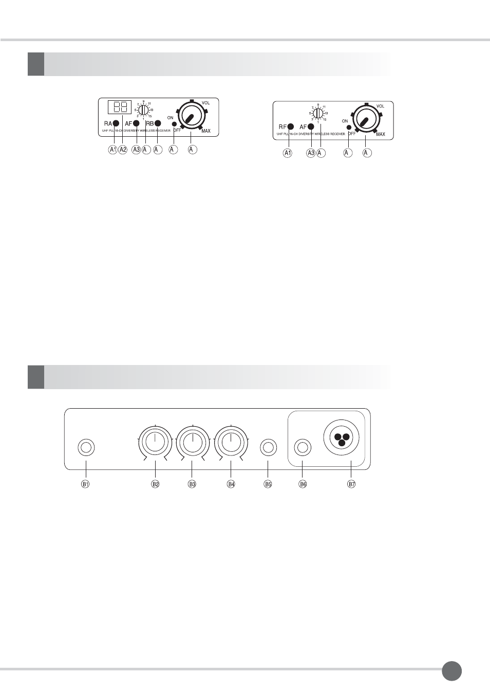
A. / Wireless Receiver Modules
2
4 5
6
7
A1. RF Signal Indicator: The yellow LED RF lights up that when wireless audio signal are being received and
transmitted.
A2. LED number display: Turn the channel selector from 1 to 16 and see the LED screen shows current channel
position. Check if transmitter turned to the same frequency then use it.
A3. AF Signal Indicator: The red LED AF lights up that microphone signal are being transmitted and received
when microphone turned on.
A4. Channel selector a. Revolving spindle of 16 users selectable channel.
A5. RA/RB: Diversity A/B indicator; the LED lights glow when the receiver detects
RF signals from the transmitter. If it is only one light glows means only one signal received from one antenna.
A6. Power ON/OFF /Volume Knob: Adjust by turning clockwise when power is on while volume up microphone.
A7. Volume control: Rotate volume knob clockwise to increase volume to desire level or counterclockwise to
decrease volume until the power switch off.
4
6
7
UDR-7F
USR-6F
Multipurpose Wireless Portable PA Amplifier System
B. Control Panel
B1. LINE OUT:
B2. MUSIC VOL.:
B3. ECHO VOL.:
B4. MIC ½ VOL.:
B5. LINE IN :
B6. MIC 1 IN
B7. XLR MIC 2 IN
VOL.
MIC1/2
VOL.
OFF
MAX.
VOL.
ON
MIC2 IN
XLR
ECHO
LINE IN
MIC1 IN
LINE IN
LINE OUT
MIN.
MAX.
MIN.
MAX.
MIN.
MAX.
disc