Rcd-1 connectors – WaveWare RCD-1 User Manual
Page 14
WaveWare
WaveWare
WaveWare
WaveWare
Paging Data Receiver
Paging Data Receiver
Paging Data Receiver
Paging Data Receiver
14
9.
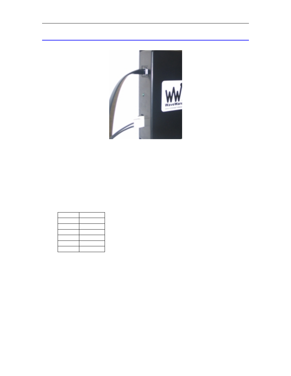
RCD-1 Connectors
Fig. 2 - RCD-1 Side View
The RCD-1 Enclosure has the following features:
9.1.
External Antenna Jack
An SMA female connector is located on the top of the RCD-1. It allows one to connect an external antenna
to the RCD-1. WaveWare includes an external antenna as standard equipment on the RCD-1.
9.2.
Power/Data Modular Connector
An RJ-12 6 pin modular positive lock connector is provided for both power and data connections to the
RCD-1. The power/data modular connector has the following functions:
Pin Function
1 +5V
Input
2 N/C
3 TXD
4 N/C
5 N/C
6 GND
The modular connector allows direct connection to an Adaptive™ LED message board using a straight
wired 6 pin modular patch cable. When using the RCD-1 to deliver RS-232 data to a PC, an optional DB9F
modular adapter is available, that combines power and data into the adapter. When using the RCD-1 only
for remote circuit switching, a power adaptor is direct connected to the power/data modular connector, and
a relay output interface harness is connected to the relay output connector (see below).
9.3.
Relay Output Connector
The relay output connector is a two pin Molex connector providing a positive lock connection between the
RCD-1’s onboard relay and external annunciation devices. An optional relay output interface harness is
available for connecting the external annunciation devices with the RCD-1 (see Fig. 2 above).
9.4. Power/Data
LED
The power/data LED indicates both power and when data is received. On powerup, the power/data LED is
always illuminated. When data is output on the serial port, the power/data LED will momentarily blink.