Figure 3 - rear panel layout – mono version – Aesthetix Atlas User Manual
Page 8
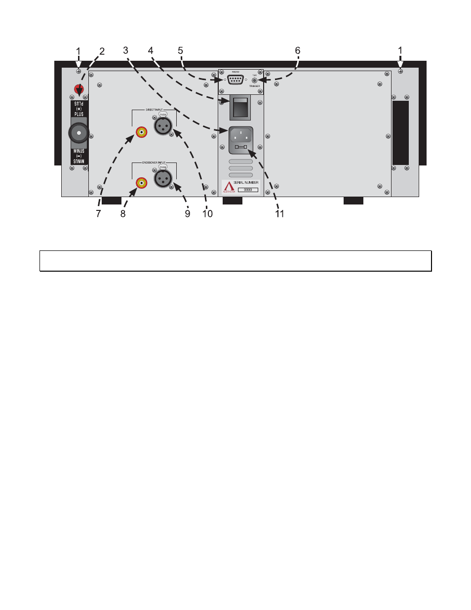
Figure 3 - Rear Panel Layout – Mono Version
Note: Figure 3 shows a Right Channel Mono Atlas. A Left Channel Mono Atlas would be identical with the
exception of the inputs and the output being on the opposite side.
1. 6-32 screws to secure the top cover. Before removing top cover, turn off rear panel MAIN POWER switch
and wait 15 minutes. Then remove the two 6-32 screws and pull up top cover from the rear panel.
2. Output
channel
BINDING POST. Connect plus and minus speaker wires for the appropriate speaker to the
appropriately marked terminals.
3. AC POWER INPUT.
4. MAIN POWER Switch. Disconnects AC to all circuits. It is recommended that this be left ON at all times
during regular use with the exception of whenever cables are connected/disconnected or when the unit is
not going to be used for an extended period of time.
5. DB9
RS232 connector. Used for connecting a system control device to the Atlas to control and monitor its
functions.
6. Remote TRIGGER jack. When the rear panel TRIGGER jack receives a 5-12 VDC pulse the Atlas will
change its mode from either standby to operate, or operate to standby, depending on its current mode.
7. Direct
Input
SINGLE ENDED input jack.
8. Crossover
Input
SINGLE-ENDED input jack.
9. Crossover
Input
BALANCED input jack.
10. Direct Input BALANCED input jack.
11. Chassis FUSE. Replace with same type and rating only. (Spare fuse inside).
8