4
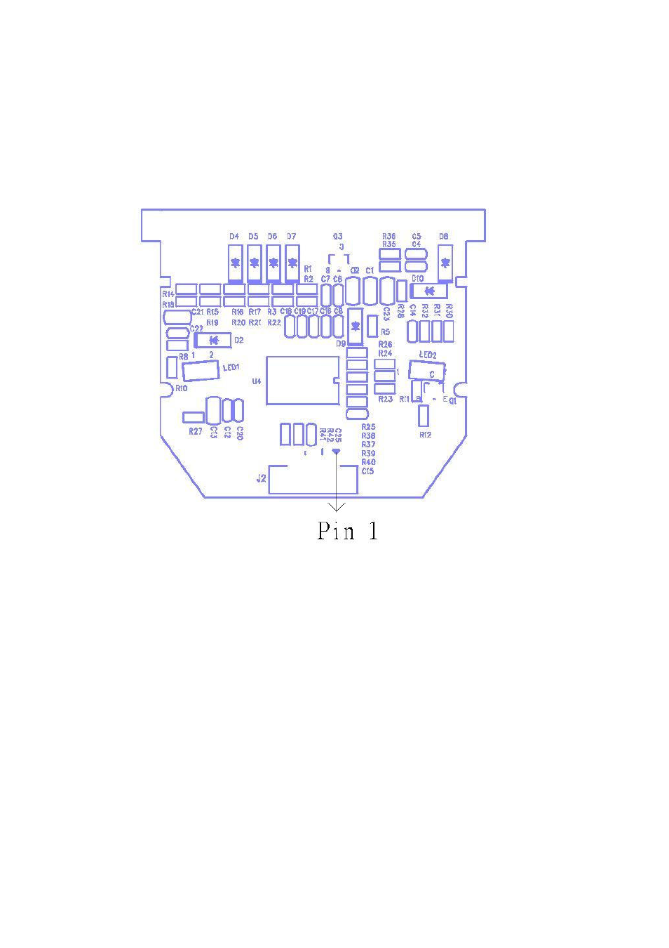
2. Signal Connector
The control module is reserved connection pins for interface, trigger, buzzer, LEDs and power. J2 is comprised of 14 pins that start from right to left, pin1 to pin 14. The diagram and description are listed as below: