J2 connector – Argox FM201 User Manual
Page 6
5
2.1. J2 Connector
Pin Description
Example
1
GND.— Supply signal ground
2
RTS ( To Host ) / CLK/KB.— TTL level
232 Request to send
3
RxD ( From Host ).— TTL level 232
receive data
4
CTS ( From Host ) / DATA/KB.— TTL
level 232 Clear to Send signal.
5
DATA/PC ( PS2 DATA ).
6
CLK/PC ( PS2 CLK ).
7
TxD ( To Host ).—TTL level 232
transmit data.
8
5 V DC input—Supply voltage input.
9
I/F identification . According to the
voltage level at I/F, the scanner will
automatically select a communication
Interface, when the interface selection of
scanner being set at auto-detection
mode.
The followings list the interface
selection corresponding to the various
voltage level at I/F.
I/F floating-NC: Identified as RS232
I/F short to GND: Identified as
Keyboard wedge. Wire I/F with a
4.7K then ground : Identified as USB
Wire I/F with a 4.7K then ground
R
4
4.
7K
/0
60
3
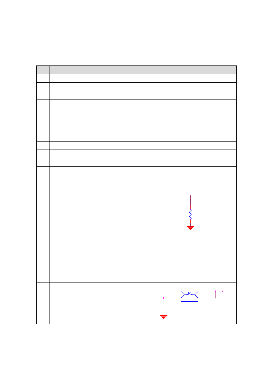
10
Trigger Switch(SW1)
To trigger off a scanning operation..
P14 of CPU is wired to the SW1 to read
the SW1 status, pressed or released.
SW1
Tack Switch
1
GND
3
GND
2
TRIGEER
4
TRIGEER
STS-KB5
SERIES