Rear panel connections, Input and output connections, Input – ART Pro Audio Tube Channel - Tube Mic Preamp/Compressor/EQ User Manual
Page 16: Output, Loop inserts, Nput and, Utput, Onnections, Nput, Nserts
15
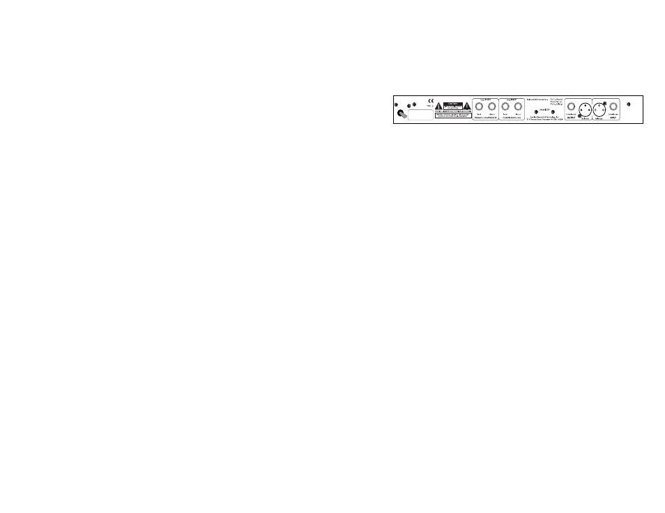
Rear Panel Connections
Input and Output Connections
The Tube Channel’s XLR connectors follow the AES standard: Pin 1
= Ground, Pin 2 = Hot (+), Pin 3 = Cold (-). The unbalanced ¼”
phone jacks are typical Tip = Hot (+), Sleeve = Ground.
Input
One input jack per channel should be used at a time. However, because
of its design, the Tube Channel can be hard-wired without having to
disconnect the XLR inputs when using the ¼” jacks. If no load is
placed on the XLR input (no instrument or microphone connected) the
¼” jack will function as if there was nothing connected to the XLR
input. However, it is still preferable to disconnect any unused cables to
avoid pick up of extraneous noise, hum, or RF interference.
Output
Both balanced and unbalanced output connections may be used
simultaneously. This is particularly useful when using the Tube
Channel as a direct box for instruments or line level signals.Note: If
you experience a hum when using both output connectors
simultaneously (one to the console and one to an instrument amp), a
ground loop may be the problem. To remedy this problem, disconnect
the ground wire (pin 1) from the XLR cable plugged into the Tube
Channel’s output (or use a ground-lifted audio cable). This interrupts
the ground path and therefore breaks the loop.
Loop Inserts
Two signal loops are provided to connect external equipment to the
Tube Channel, to use only specific individual circuits, or to take direct