Maps and registers, 1 interrupt structure, Figure 6-1 – Artesyn ATCA 7370 / ATCA 7370-S Installation and Use (June 2014) User Manual
Page 115: Interrupt structure on atca-7370, Chapter 6
Chapter 6
ATCA-7370/ATCA-7370-S Installation and Use (6806800P54F)
115
Maps and Registers
6.1
Interrupt Structure
The ATCA-7370 supports NON-APIC (legacy PIC Mode) and APIC mode of Interrupt delivery to
the CPUs. The 8259 PIC mode interrupt concentrator supports 16 interrupts (8 external signal
inputs). The IO-APIC device supports 24 interrupt sources. In APIC mode the C604 chipset
supports only Front side bus interrupt delivery (not the serial APIC mode). The following figure
and tables summarize the interrupt sources and mappings for ATCA-7370. APIC mode is
configured through BIOS after boot-up phase which is done in legacy PIC mode.
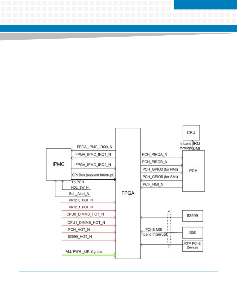
The following diagram shows the interrupt signals connection and possible interrupt
resources:
Figure 6-1
Interrupt Structure on ATCA-7370