Table 3-3, J20/p20 connector pin assignments for atca-7350, Controls, leds and connectors – Artesyn ATCA-7350 Installation and Use (September 2014) User Manual
Page 65
Controls, LEDs and Connectors
ATCA-7350 Installation and Use (6806800G59G)
65
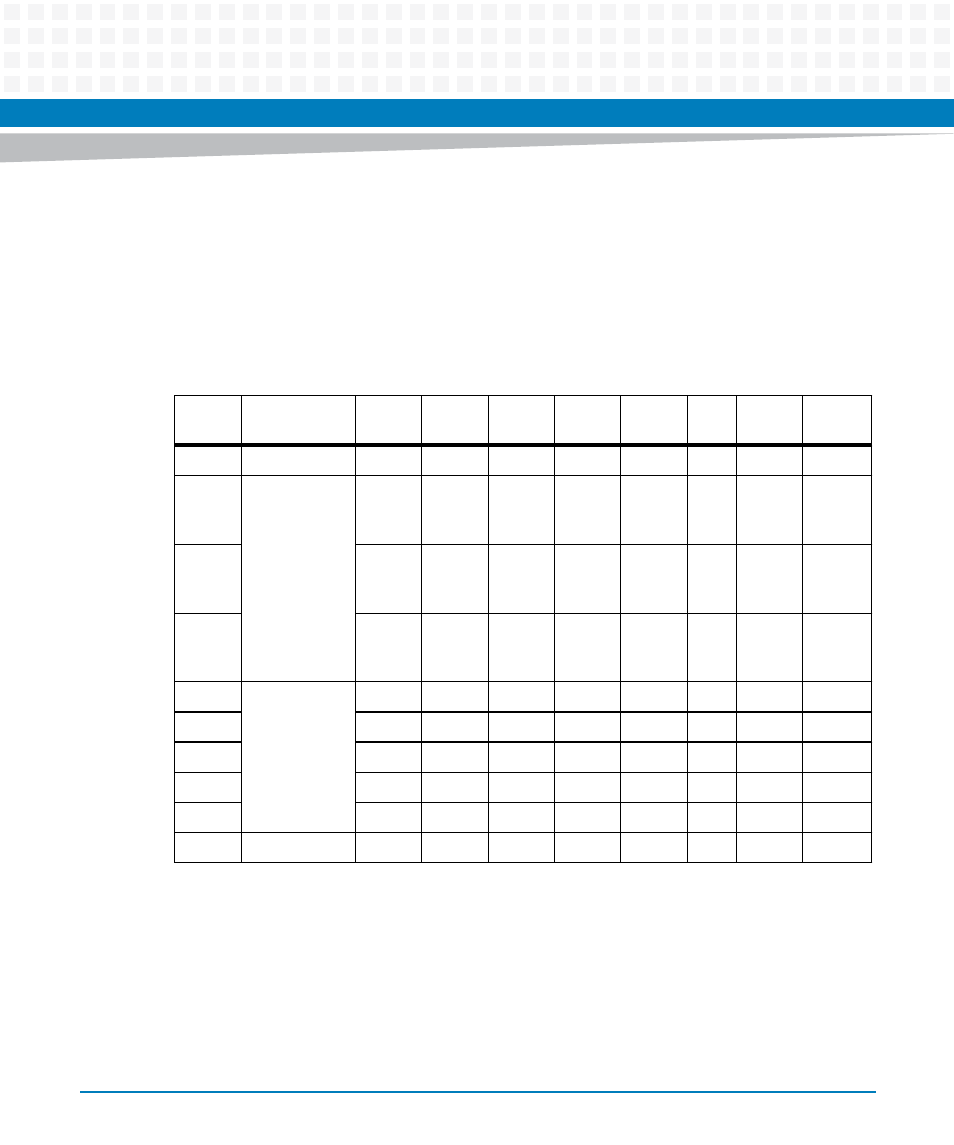
The connector pin assignments are described in the table as below with signals having the
following naming convention: UP(m)Tx/ Rx p, where:
Tx/Rx = transmit/receive
m = Channel designator (1-4)
p = polarity (+,-)
All the tx/rx signals are as seen from ATCA-7350 side.
The two Fabric interface channels and two Base interface channels supported by the ATCA-
7350 are on the P23 of Zone 2.
shows the positions of Fabric Channel 1 and Channel 2, Base Channel 1 and Channel
2 on the P23.
Table 3-3 J20/P20 Connector Pin Assignments for ATCA-7350
Pin
Interface
Designation
A
B
C
D
E
F
G
H
1
CLKs
NC.
NC.
NC.
NC.
NC.
NC.
NC.
NC.
2
Update
Channel
NC.
NC.
Term.
UP(4)R
x+
Term.
UP(4)R
x-
NC.
NC.
NC.
NC.
3
NC.
NC.
Term.
UP(2)R
x+
Term.
UP(2)R
x-
NC.
NC.
Term.
UP(3)R
x+
Term.U
P(3)Rx-
4
UP(0)T
x+
UP(0)T
x-
UP(0)R
x+
UP(0)R
x-
NC.
NC.
Term.
UP(1)R
x+
Term.U
P(1)Rx-
5
Fabric
Channels 15-
13
(Unused.)
NC.
NC.
NC.
NC.
NC.
NC.
NC.
NC.
6
NC.
NC.
NC.
NC.
NC.
NC.
NC.
NC.
7
NC.
NC.
NC.
NC.
NC.
NC.
NC.
NC.
8
NC.
NC.
NC.
NC.
NC.
NC.
NC.
NC.
9
NC.
NC.
NC.
NC.
NC.
NC.
NC.
NC.
10
NC.
NC.
NC.
NC.
NC.
NC.
NC.
NC.