2 smt configuration switch (s2), Table 3-20, Geographical address switch settings – Artesyn MVME2500 ECC Installation and Use (August 2014) User Manual
Page 65: Figure 3-6, Smt configuration switch position, Controls, leds, and connectors
Controls, LEDs, and Connectors
MVME2500-ECC Installation and Use (6806800N30F)
65
3.5.2
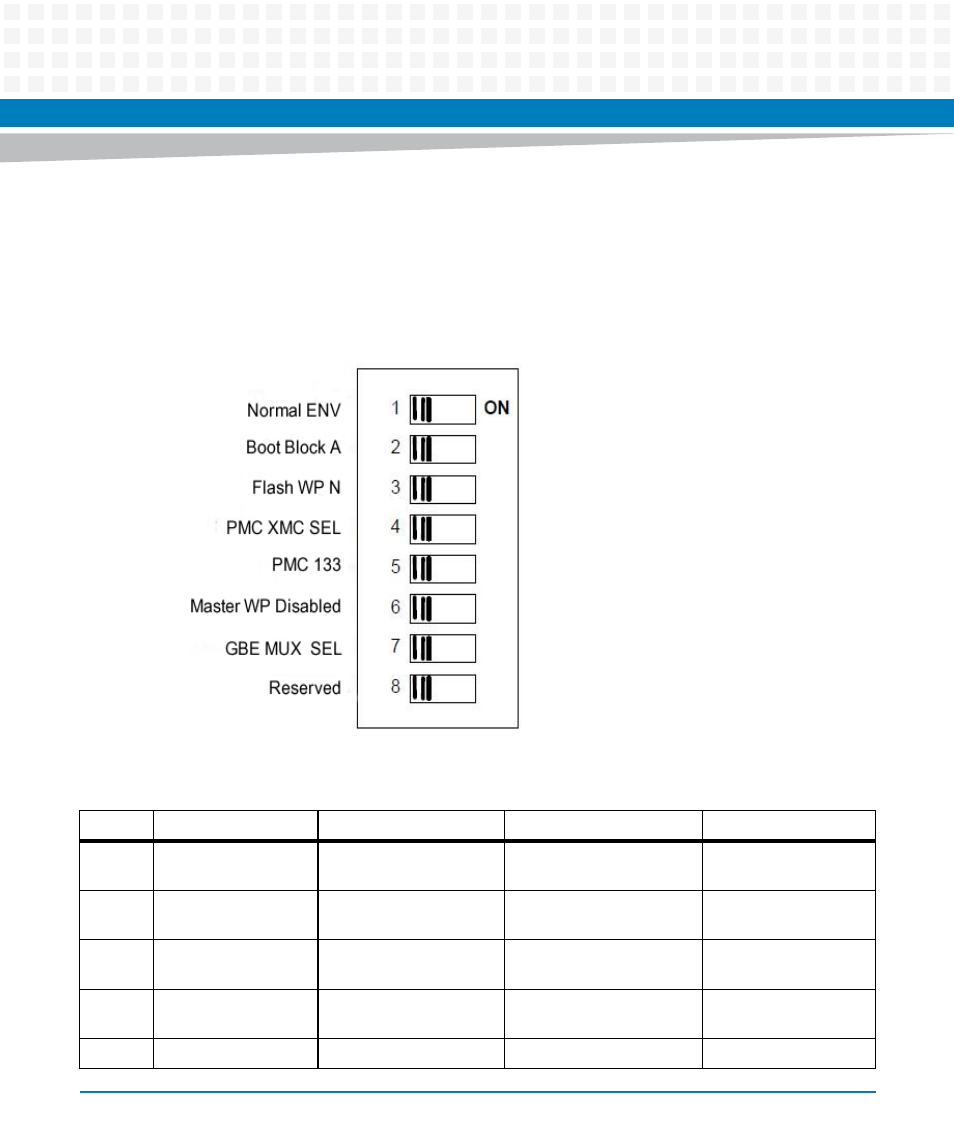
SMT Configuration Switch (S2)
This eight position SMT configuration switch controls the flash bank write-protect, selects the
flash boot image, and controls the safe start ENV settings. The default setting on all switch
positions is "OFF" and is indicated by brackets in
.
Figure 3-6
SMT Configuration Switch Position
Table 3-20 Geographical Address Switch Settings
SW2
DEFAULT
Signal Name
Description
Notes
1
OFF (Normal Env)
NORMAL_ENV=switch is
OFF
Safe Start= switch is ON
2
OFF (Flash Block A)
FLASH_BOOT_BLOCK A
= switch is OFF
FLASH_BOOT_BLOCK B =
switch is ON
3
OFF (WP Disabled)
WP_Disabled = switch is
OFF
SPI Flash Write-Protect
4
OFF EEPROM_WP_Disabled
=
switch is OFF
EEPROM_WP_Disabled =
switch is ON
5
OFF (133 MHz)
PMC_133
PCI frequency selection