Table 5-2, Ethernet connectors pin assignment, Table 5-3 – Artesyn MVME3100 Single Board Computer Installation and Use (June 2014) User Manual
Page 87: Pmc slot 1 connector (j11) pin assignments, Pin assignments
Pin Assignments
MVME3100 Single Board Computer Installation and Use (6806800M28E)
87
5.2.2
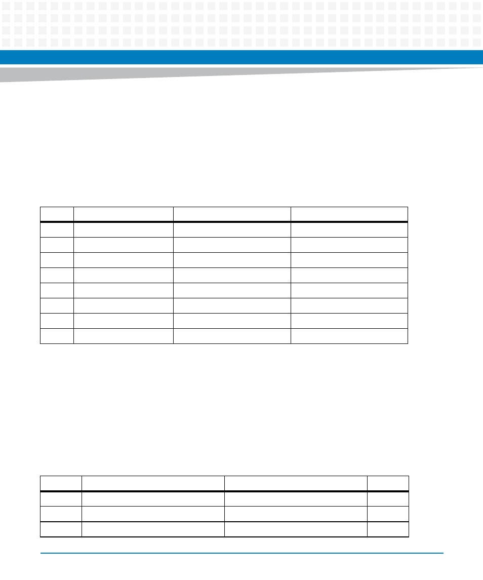
Ethernet Connectors (GENET1/J41B, GENET2/J2B, ENET1/J2A)
There is one 10/100 and two 10/100/1000Mb/s full duplex Ethernet interfaces using the
MPC8540 Fast Ethernet Controller (FEC) and two Triple Speed Ethernet Controllers (TSEC). One
Gigabit Ethernet interface is routed to a front-panel RJ-45 connector with integrated LEDs for
speed and activity indication. The other Gigabit Ethernet interface and the 10/100 interface
are routed to P2 for rear I/O. The pin assignments for these connectors are as follows:
5.2.3
PCI Mezzanine Card (PMC) Connectors (J11 – J14, J21 – J23)
There are seven 64-pin SMT connectors on the MVME3100 to provide 32/64-bit PCI interfaces
and P2 I/O for one optional add-on PMC.
PMC slot connector J14 contains the signals that go to VME P2 I/O rows A, C, D, and Z.
The pin assignments for these connectors are as follows.
Table 5-2 Ethernet Connectors Pin Assignment
Pin #
Signal
1000 Mb/s
10/100 Mb/s
1
MDIO0+
_DA+
TD+
2
MDIO0-
_DA-
TD-
3
MDIO1+
_DB+
RD+
4
MDIO1-
_DC+
Not Used
5
MDIO2+
_DC-
Not Used
6
MDIO2-
_DB-
RD-
7
MDIO3+
_DD+
Not Used
8
MDIO3-
_DD-
Not Used
Table 5-3 PMC Slot 1 Connector (J11) Pin Assignments
Pin
Signal
Signal
Pin
1
TCK
-12V
2
3
GND
INTA#
4
5
INTB#
INTC#
6