Table 5-20, Front/rear, Pin assignments – Artesyn MVME6100 Single Board Computer Installation and Use (June 2014) User Manual
Page 103
Pin Assignments
MVME6100 Single Board Computer Installation and Use (6806800D58H)
103
5.3.5
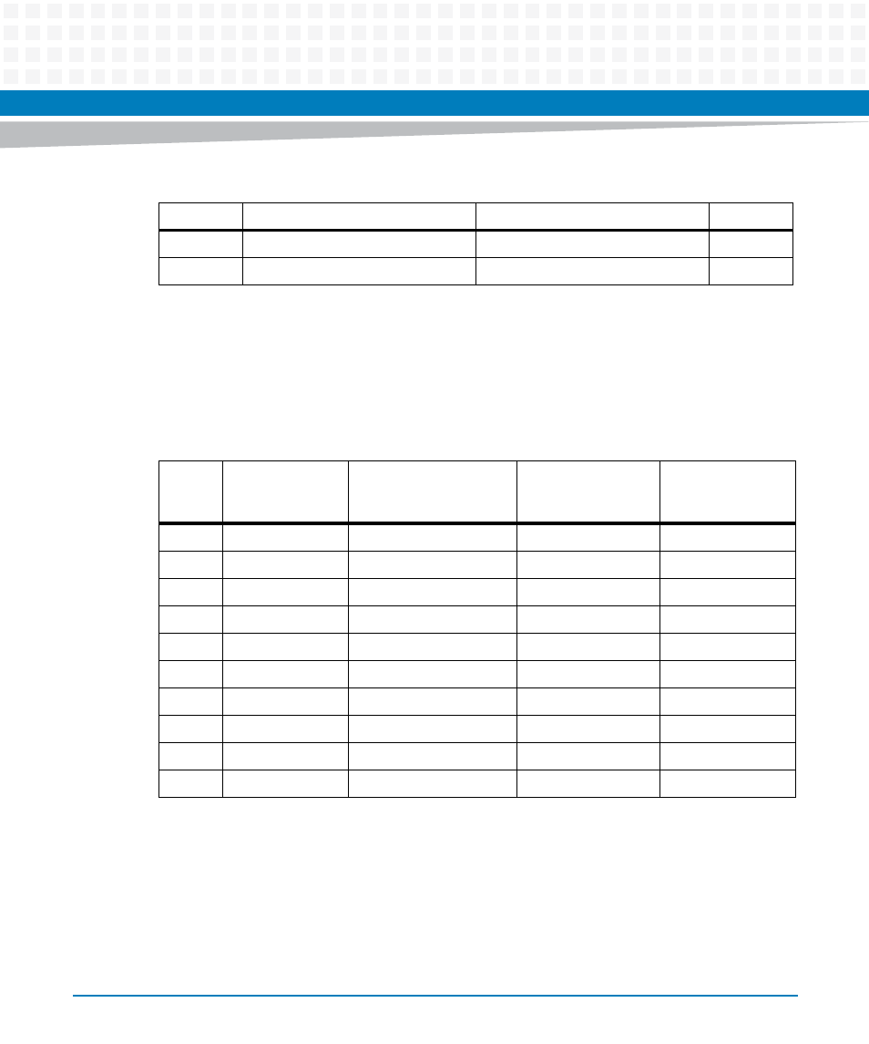
Front/Rear Ethernet and Transition Module Options Header
(J30)
The pin assignments for this connector are as follows:
7
COM2_DTR
COM2_RI
8
9
GND
KEY (no pin)
10
Table 5-19 COM2 Planar Serial Port Header (J29) Pin Assignments (continued)
Pin
Signal
Signal
Pin
Table 5-20 Front/Rear Ethernet and Transition Module Options Header (J30) Pin Assignment
Pin
Row D
(From PMC I/O)
Row C
(To P2 Connector)
Row B
(From LAN2
Controller)
Row A
(To Front Panel
Ethernet)
1
PMC0_IO(13)
P2
a
_C7
a. VME P2.
Fused +12V
No Connect
2
PMC0_IO(60)
P2_A30
Fused -12V
No Connect
3
PMC0_IO(7)
P2_C4
magnetic T2
b
-23
b. Transformer for Ethernet port #2.
MDI_0P (J9
c
-2)
c. Ethernet port #2 front connector.
4
PMC0_IO(5)
P2_C3
magnetic T2-22
MDI_0N (J9-3)
5
PMC0_IO(3)
P2_C2
magnetic T2-20
MDI_1P (J9-4)
6
PMC0_IO(1)
P2_C1
magnetic T2-19
MDI_1N (J9-5)
7
PMC1_IO(38)
P2_Z25
magnetic T2-17
MDI_2P (J9-6)
8
PMC1_IO(41)
P2_Z27
magnetic T2-16
MDI_2N (J9-7)
9
PMC1_IO(44)
P2_Z29
magnetic T2-14
MDI_3P (J9-8)
10
PMC1_IO(46)
P2_Z31
magnetic T2-13
MDI_3N (J9-9)