A.2 pcie-8120 card edge connector, Table a-1, Pcie-8120 card edge connector pin out – Artesyn PCIE-8120 Installation and Use (July 2014) User Manual
Page 51: Pcie-8120 card edge connector, Pcie-8120 external connectors
PCIE-8120 External Connectors
PCIE-8120 Installation and Use (6806800R89C)
51
A.2
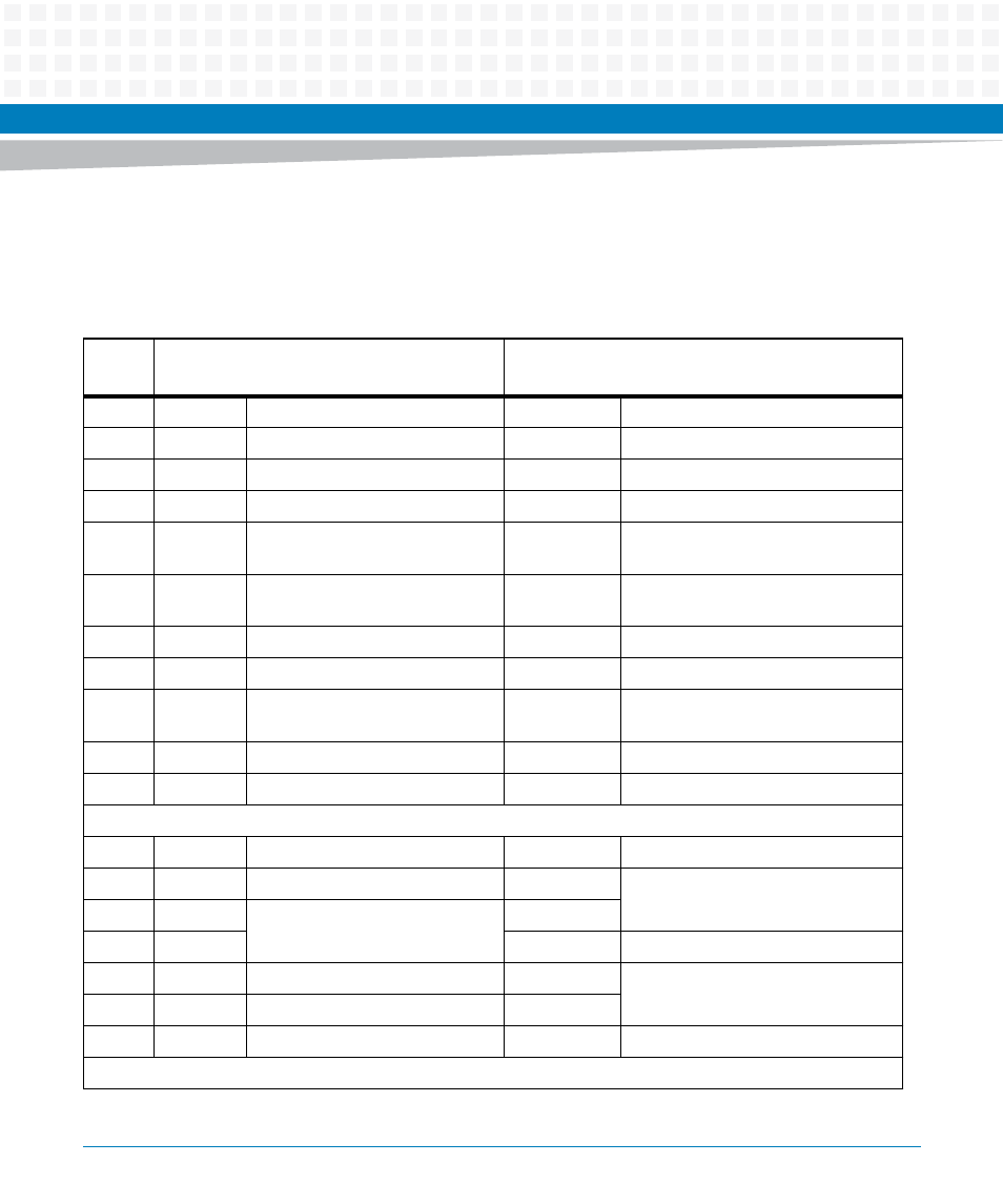
PCIE-8120 Card Edge Connector
The following table provides pin assignment for the PCIE-8120 card edge connector:
Table A-1 PCIE-8120 Card Edge Connector Pin out
Pin
#
Side B
Name Description
Side A
Name Description
1
+12V
12V power
PRSNT1#
Hot-Plug presence detect
2
+12V
12V power
+12V
12V power
3
+12V
12V power
+12V
12V power
4
GND
Ground
GND
Ground
5
SMCLK
SMBus (System management
Bus) clock
JTAG2
TCK (Test Clock), clock input for JTAG
interface
6
SMDAT
SMBus (System management
Bus) data
JTAG3
TDI (Test Data Input)
7
GND
Ground
JTAG4
TDO (Test Data Output)
8
+3.3V
3.3V power
JTAG5
TMS (Test Mode Select)
9
JTAG1
TRST# (Test Reset) resets the JTAG
interface
+3.3V
3.3V power
10
3.3Vaux
3.3V auxiliary power
+3.3V
3.3V power
11
WAKE#
Signal for Link reactivation
PERST#
Fundamental reset
Mechanical Key
12
RSVD
Reserved
GND
Ground
13
GND
Ground
REFCLK+
Reference clock
(differential pair)
14
PETp0
Transmitter differential pair,
Lane 0
REFCLK-
15
PETn0
GND
Ground
16
GND
Ground
PERp0
Receiver differential pair,
Lane 0
17
PRSNT2#
Hot-Plug presence detect
PERn0
18
GND
Ground
GND
Ground
End of the x1 connector