Basler Electric VR63-4/UL User Manual
Basler Electric Accessories for electrical
BASLER ELECTRIC,
BOX 269,
HIGHLAND, IL 62249
PHONE 618/654-2341
FAX 618/654-2351
INTRODUCTION
The VR63-4/UL Voltage Regulators are
designed for use on 50/60 Hz brushless
generators. The regulator includes frequency
compensation, overexcitation shutdown, a
solid-state build-up circuit, and EMI filtering.
WARNING
To prevent personal injury or equipment
damage, only qualified technicians or
operators should install, operate, or
service this device.
ELECTRICAL SPECIFICATIONS
Dc Output Power:
4 Adc at 63 Vdc (252W) maximum continuous,
7 Adc at 100 Vdc (700W) forcing one minute
(at 240 Vac input).
Exciter Field Dc Resistance:
15 ohms minimum; 100 ohms maximum.
Ac Power Input:
Operating range: 190 Vac to 240 Vac, +10%
Single phase, 50/60 Hz, Burden 500 VA.
Sensing Input:
190-240 Vac, Single phase, 50/60 Hz +10%,
common with AC Power Input.
Voltage Adjust Range:
171-264 Vac.
Regulation Accuracy:
Better than ±1.0% no load to full load.
Response Time:
Less than 1.5 cycles for +10% change in
sensing voltage.
EMI Suppression:
Internal electromagnetic interference filter
(EMI filter).
Overexcitation Shutdown:
Output power is removed under the following
conditions: Exciter field voltage exceeds
100+5 Vdc for a time inversely proportional to
voltage magnitude, or instantaneously if the
exciter field voltage exceeds 135+5 Vdc.
Voltage Build-up:
Internal provisions for automatic voltage build-
up from generator residual voltages as low as
10 Vac.
Power Dissipation:
8 Watts maximum.
PHYSICAL SPECIFICATIONS
Operating Temperature:
-40
C (-40 F) to +60 C (+140 F).
Storage Temperature:
-65
C (-85 F) to +85 C (+185 F).
Vibration:
Withstands 1.3 Gs at 2 to 27 Hz; 0.036"
double amplitude at 27 to 52 Hz; and 5 Gs at
52 to 1000 Hz.
Shock:
Withstands up to 20 Gs in each of three
mutually perpendicular axes.
Weight:
14 oz. (0.40 kg) Net.
CSA Approved/UL Recognized
FUSES
It is recommended that fuses with high
interruption capability be installed per the inter-
connection diagram to protect wiring from
faults before the regulator. Refer to the
Interconnection Drawings.
NOTE
Fuse must be installed per the
interconnection diagrams to avoid inter-
rupting the field current.
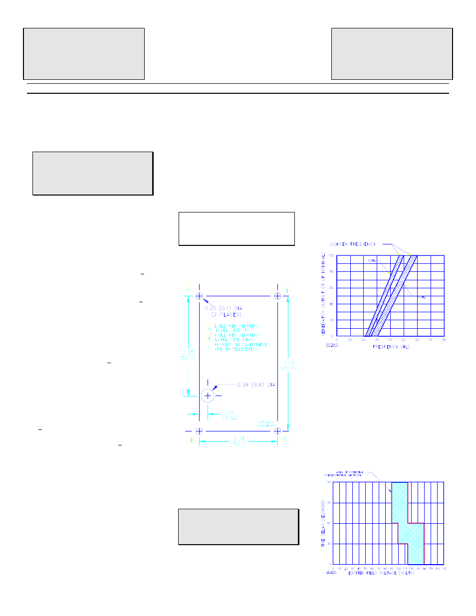
MOUNTING
The regulator may be mounted in any position.
Refer to the drilling diagrams.
Drilling Diagram
EXCITER FIELD POWER CIRCUIT (wires F+
and F-).
Connect the regulator wire F+ to the brushless
exciter field terminal F+, and wire F- to
terminal F-.
CAUTION
The dc resistance of the exciter field must
be equal to or greater than 15 ohms and
less than 100 ohms.
POWER/SENSING INPUT CIRCUIT (wires 3
and 4)
Connect as shown by the Interconnection
Diagrams.
Power for the exciter field and regulator
circuitry is derived from the generator output or
auxiliary winding. The operable power input
range is 171 to 264 Vac and is connected to
Terminals 3 and 4.
FREQUENCY COMPENSATION
The frequency compensation characteristic is
to improve system load pickup performance by
restraining voltage recovery until frequency
has also started to recover.
For 50 Hz system, the regulator is preset at
the factory for a 45 Hz “corner frequency”.
For 60 Hz systems, a 55 Hz “corner
frequency”. is achieved by cutting the external
Hz jumper wires on the generator. Be sure to
insulate the the two wires so that they are not
exposed.
Frequency Compensation Curves
OVEREXCITATION SHUTDOWN
If the exciter field voltage exceeds 100 ±5 Vdc,
the regulator automatically removes the field
current after a time delay. The time delay is
inversely proportional to the magnitude of the
detected overvoltage condition up to the 135
Vdc point. Beyond 140 Vdc, the field voltage
is removed within 0.2 seconds.
After shutdown, reset the regulator by
decreasing voltage below 6 Vac either by
stopping the prime mover or interrupting the
regulator input with a reset switch for 2
seconds or more.
Typical Time Delay Characteristic Curves
CONFIDENTIAL INFORMATION
OF BASLER ELECTRIC COMPANY, HIGHLAND, IL.
IT IS LOANED FOR CONFIDENTIAL USE, SUBJECT
TO RETURN ON REQUEST, AND WITH THE
MUTUAL UNDERSTANDING THAT IT WILL NOT BE
USED IN ANY MANNER DETRIMENTAL TO THE
INTEREST OF
BASLER ELECTRIC COMPANY.
Publication:
9 1668 00 994
© 1998, Basler Electric Co., Highland, IL 62249
First Printing March 1984
Revision: J
September 1998
ECO: 143
INSTRUCTION MANUAL
FOR
VOLTAGE REGULATOR
Model: VR63-4/UL