Basler Electric VR63-4/UL User Manual
Page 2
VOLTAGE ADJUST RHEOSTAT
Screwdriver adjustable potentiometer adjusts
generator output voltage. Adjustment CW
increases voltage.
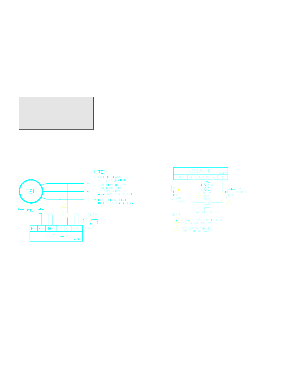
When using remote voltage adjust rheostat
(VAR), the VAR wire on the regulator should
be cut and the rheostat connected to both
ends. A 1 kohm and 1/2 watt resistance is
adequate for most applications. See
Interconnection Diagrams.
OPERATION
The following system operation procedures
provide instructions for adjusting the VR63-
4/UL Voltage Regulator.
CAUTION
Meggers and high potential test
equipment must not be used. Incorrect
use of such equipment could damage the
semiconductors contained in the
regulator.
PRELIMINARY SET-UP
To prevent damage to the regulator, complete
the following steps before proceeding with
system start-up.
a. Verify that the voltage regulator
specification conforms with the generator
system requirements.
b. Ensure that the regulator is correctly
connected to the generator. See
Interconnection Diagram.
c.
Install fuses per FUSES paragraph.
d.
Set the regulator VAR fully CCW and the
remoteVAR (if used) to centered.
SYSTEM START-UP
a. Start the prime mover and bring up to
rated speed. Voltage should buildup. If a
minimum residual of 6 Vac is not present,
perform field flashing.
b. Slowly adjust VAR CW until voltage
reaches nominal value. If used, adjust
remote voltage adjust to set generator
output to exact value desired.
OPERATIONAL TEST
a.
Connect the test setup as shown in
Operational Test. Do not apply power.
Ensure that light bulbs are rated for 120
V and less than 100 W.
b.
Adjust regulator VAR and/or remote VAR
to maximum CCW.
c.
Apply 240V, 60 Hz power to regulator.
d. Slowly adjust the regulator VAR control
CW.
RESULT:
1) Before minimum brilliance is reached, the
light bulb should attain maximum brilliance to
signify the regulating point.
2) At the regulating point, a small change in
the VAR should turn the light bulb on or off.
FIELD FLASHING
When the regulator is operated with the
generator for the first time, the polarity of
residual magnetism may not correct or the
magnitude not enough. If the generator does
not build-up after startup, shut down the prime
mover and proceed with the following steps:
a.
With the prime mover at rest, apply a dc
source (not grounded) of not more than
12V, to terminals F+(positive) and F-
(negative) in series with a limiting resistor
of 3-5 ohms.
b. Allow approximately 3 seconds before
removing the dc source.
c.
Start prime mover and measure voltage
at regulator leads 3 and 4. If voltage is
greater than 6 volts, voltage build-up
should be successful. Repeat field
flashing procedure if less than 6 V
residual is measured.
d.
If repeating steps 1 and 2 does not result
in generator voltage build-up, replace the
voltage regulator.
Interconnection Diagram, 208-240 V Nominal
Operational Test