Baumatic BWDI126N User Manual
Page 33
33
SETTING UP + INSTALL
T
T
A
L
L TIO
A
A
N
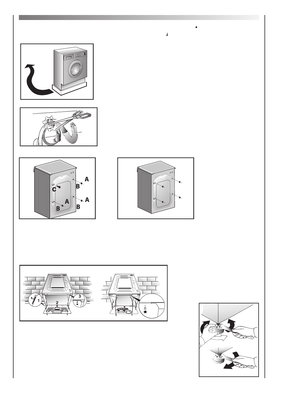
Remove the polystyrene base and place the machine near
its permanent position (diagram 1).
Carefully cut through the hose retaining clip at the rear of
the appliance (diagram 2).
Remove the 3 fixing screws marked (A) and remove the 3
spacers marked (B) (diagram 3).
Remove the screw (C).
A spacer will fall inside the machine.
By tilting the machine, remove the above mentioned spacer.
Cover the 4 holes using the caps provided in the instruction
booklet pack (diagram 4).
WARNING
W
W
:
DO NOT LEAVE
A
A
THE PACKAGING WITHIN REACH OF CHILDREN
P
P
AS IT IS A POTENTIAL
SOURCE OF DANGER.
Apply the insulation sheet of corrugated material to the base
as shown.
Use the 4 feet to level the machine with the floor:
a) Turn the nut clockwise to release the screw adjuster on the foot.
b) Rotate the foot to raise or lower it until it stands firmly on the
ground.
c) Lock the foot in position by turning the nut
anti-clockwise until it comes up against the bottom of the machine.
A
B
B
C
2
3
4
1
3
4
WARNING:
DO NOT LEAVE THE PACKAGING WITHIN REACH OF CHILDREN AS IT IS A POTENTIAL
SOURCE OF DANGER.
Apply the insulation sheet of corrugated material to the base as shown.
Use the 4 feet to level the machine with the floor:
a) Turn the nut clockwise to release the screw adjuster on the foot.
b) Rotate the foot to raise or lower it until it stands firmly on the
ground.
c) Lock the foot in position by turning the nut
anti-clockwise until it comes up against the bottom of the machine.
A
B
C
Type 1
Type 2