6 connections – BECKHOFF CX25000020 User Manual
Page 16
Mounting and wiring
3.6
Connections
Notice
Adjusting the BIOS setting
After connecting the hardware, change the Azalia configuration from DISABLED to
ENABLED in the BIOS chipset to make sure the interface is detected. Further information
can be found in the BIOS description of the CX2000 documentation.
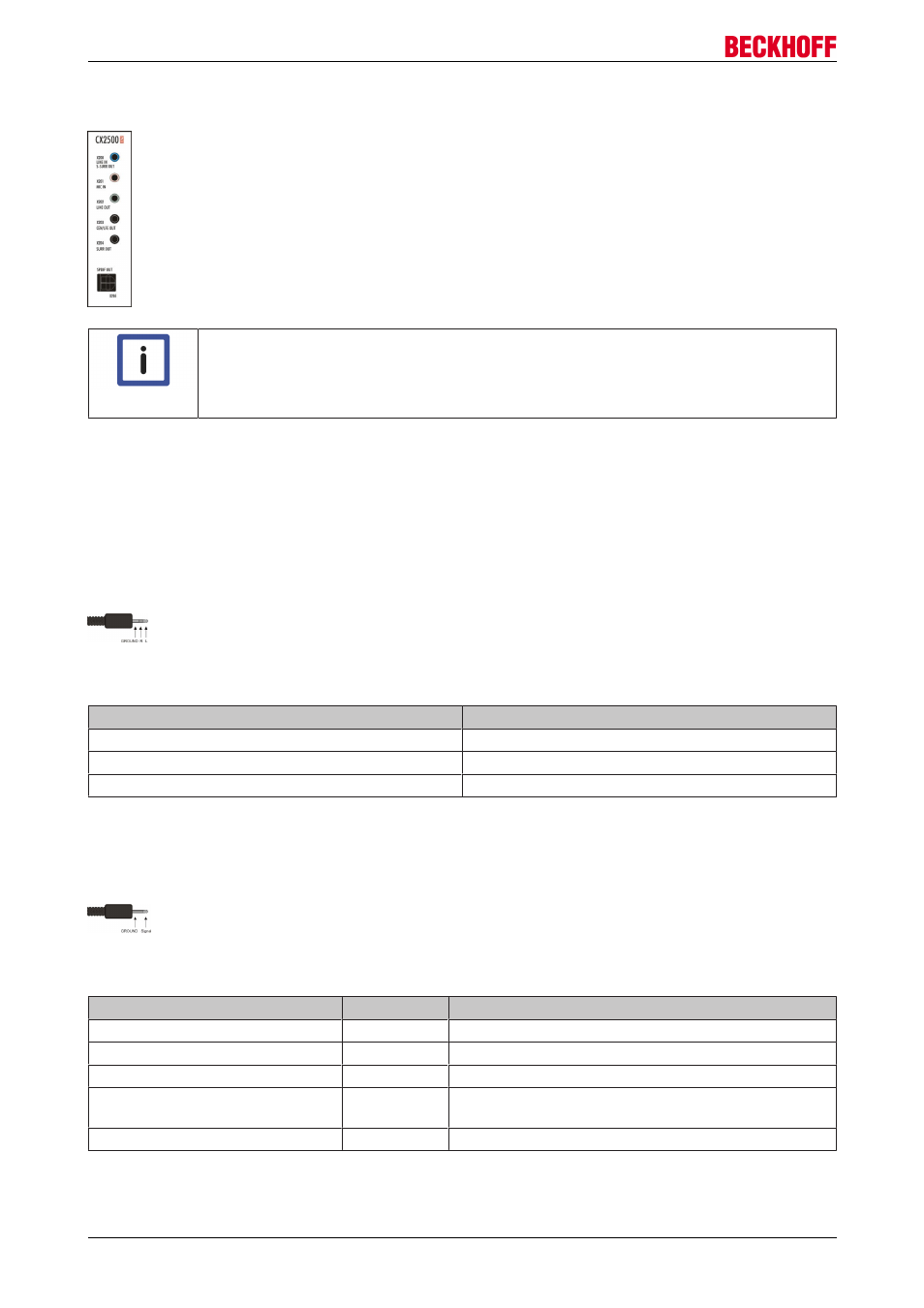
Connectors for audio devices
The CX25000020 devices extend the CX20x0 system with audio interfaces with 5 jack plugs and a Toslink
connector for digital signals (SPDIF). Up to 7.1 multichannel audio can be used.
A "LINE IN" input and five outputs (4 x "LINE OUT" and 1 x "SPDIF OUT") are available. LINE OUT (x202)
can also be used for connecting headphones with a maximum output of 200 mW. The audio interfaces are
accessed via the operating system. The 3.5 mm sockets are designed for jack plugs.
LINE IN /LINE OUT stereo jack plug (X200/X202/X203/X204):
The audio module operates in stereo mode as standard.
Table 1: Pin assignment Line In /Line Out:
Signal
Description
L
Left channel
R
Right channel
Ground
Ground
The left channel is transferred via the tip of the jack plug, the right channel via the first ring. The remainder of
the sleeve is used for earthing.
MIC IN mono jack plug (X201):
The only existing channel is transferred via the tip, the remainder of the sleeve is used for earthing.
Table 2: Plug colour code:
Socket
Description
LINE IN, SSURR OUT
X200
Line level, stereo input
MIC IN
X201
Mono or stereo microphone input
LINE OUT
X202
Front speakers, headphones, stereo output
CEN/LFE out black (normally
orange)
X203
Subwoofer and center, stereo output
SURR OUT black
X204
Rear speakers stereo output
SPDIF OUT (x205):
TOSLINK connector for digital signals.
CX25000020
16
Version 1.0