BECKHOFF C9900-G0xx User Manual
Page 19
Special instructions for the TwinCAT System Manager
C9900-G0xx
17
3 Special instructions for the TwinCAT System
Manager
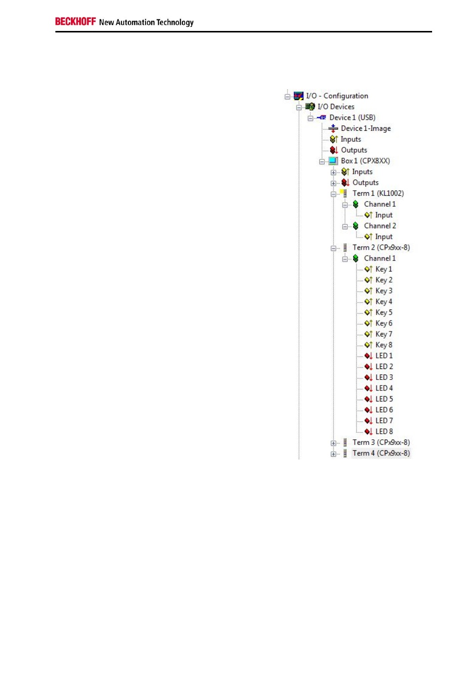
The push-button extension can be integrated via the search
function in the System Manager. The PCBs in use are shown
as terminals in the System Manager (see Fig. 10).
KL1002 stands for the emergency off PCB. Channel 1 is the
N/O contact actuated by the emergency stop. Channel 2 is
not used.
The terminals following the KL1002 represent the button
PCBs used in the configuration. The number of displayed
inputs and outputs is independent of the number of buttons
on a PCB.
For a three-button PCB the inputs “Button 1” to “Button 3”
correspond to the N/O contacts that are actuated by the
respective buttons. The inputs “Button 4” to “Button 6”
correspond to the digital inputs that are allocated for
customer use. “Button 7” and “Button 8” are not used. The
outputs “LED 1” to “LED 3” are connected to the indicator
lamps. “LED 4” to “LED 8” are not used.
For a four-button PCB the inputs “Button 1” to “Button 4”
correspond to the N/O contacts that are actuated by the
respective buttons. “Button 5” to “Button 8” correspond to the
digital inputs that are allocated for use by the customer. “LED
1” to “LED 4” are connected to the indicator lamps. “LED 5” to
“LED 8” are not used.
Since it is not directly apparent from the diagram which PCB
is at which location, section 7.3 of the annex contains an
overview of PCB combinations for different devices. Please
note that in cases where three- and four-button PCBs are
combined, the three-button PCBs are always listed first.
Fig. 13: Push-button extension in the System
Manager