BECKHOFF FM33xx User Manual
Page 33
Register description
28
FM33xx
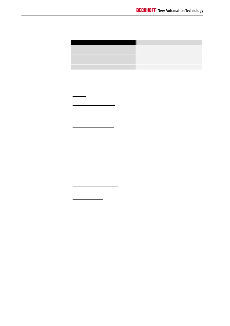
The structure of a register set is divided into the following areas:
Range
Address
Process variables
0-7
Type register
8-15
Manufacturer parameters
16-30
User parameters
31-47
Extended user region
48-63
Process variables
R0-R7 Registers in the terminal's internal RAM:
The process variables can be used in addition to the actual process image.
Their function is specific to the terminal.
R0-R5: The function of these registers depends on the type of terminal.
R6: Diagnostic register
The diagnostic register can contain additional diagnostic information. Parity
errors, for instance, that occur in a serial interface during data transmission
are indicated here.
R7: Command register
High-Byte_Write = function parameter
Low-Byte_Write = function number
High-Byte_Read = function result
Low-Byte_Read = function number
Type register
R8-R15 Registers in the terminal's internal ROM:
The type and system parameters are hard programmed by the
manufacturer, and the user can read them but cannot change them.
R8: Terminal type:
The terminal type in register R8 is needed to identify the terminal.
R9: Software version X.y
The software version can be read as a string of ASCII characters.
R10: Data length
R10 contains the number of multiplexed shift registers and their length in
bits.
The Bus Coupler sees this structure.
R11: Signal channels
Related to R10, this contains the number of channels that are logically
present. Thus for example a shift register that is physically present can
perfectly well consist of several signal channels.
R12: Minimum data length
The particular byte contains the minimum data length for a channel that is
to be transferred. If the MSB is set, the control/status byte is not absolutely
necessary for the terminal's function, and if the coupler is appropriately
configured it is not transferred to the controller.