9 ...... set up – BUG-O Systems SPB-3000 User Manual
Page 9
9
SETUP
INSTALL THE RAIL
1.
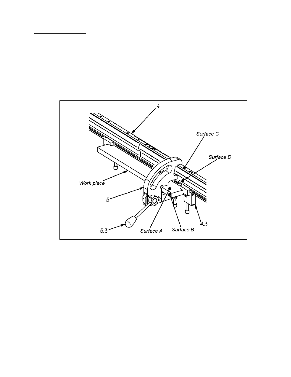
Position the rail (4) onto the work piece. The carriage should be on the edge of the rail, i.e.
outside of the work area.
2.
Align the rail using the alignment clamps (5). Surfaces A and B of the work piece and
surfaces C and D of the rail should be in contact with corresponding alignment clamp
surfaces, as shown in Figure 8.
3.
Secure the rail to the work piece. Fasten the alignment clamps by lowering lever (5.3).
4.
Position the end clamps (4.3) on each side of the work piece and tighten the clamp
screws. This prevents the rail from moving during beveling, when the alignment clamps are
being moved.
INSTALL THE MILLING UNIT
After mounting the rail, secure the milling unit holder with milling unit onto the carriage.
NOTE: Numbers in parentheses () correspond to labels in Figures 2-7.
1.
Hold the milling unit (2) so the milling head (2.5) is facing upward.
2.
Turn drive ring lever (2.4) clockwise until it stops.
3.
Select the proper milling unit holder (3) for the desired bevel angle.
4.
Loosen the bevel depth interlock (3.2).
5.
Align the bevel depth interlock with the slot in the milling head casing (2.2) and slide
milling unit holder onto milling unit.
6.
Turn drive ring lever counterclockwise to set bevel depth. (Scale = 1 mm)
Note: It is advisable to begin with minimal bevel depth, especially at the 0º angle.
7.
Tighten bevel depth interlock.
8.
Loosen interlock screws (1.4) on carriage (1).
9.
Slide milling unit holder into place.
10.
Tighten interlock screws to hold milling unit and holder in place while bevelling.
11.
Plug the milling unit into the power supply connection (1.10) on the carriage.
Figure 8: Position of rail on work piece.