Bug-5100-f dc iii drive unit, Exploded view / bug-5100-f dc iii drive unit – BUG-O Systems CON-O User Manual
Page 9
9
DRIVE UNIT OPERATION
Rotating Cam Knob (B) will move the drive pinion in and out of engagement
with the ring gear.
To lock drive into position, tighten the 1/4-28
Wing Nut (A).
To disengage the drive pinion from the ring gear, loosen the 1/4-28
Wing
Nut (A) and turn Knob (B) counterclockwise. Turn Knob (B) clockwise to
engage the drive pinion with the ring gear, retighten the 1/4-28
Wing Nut (A)
to lock position.
When
Power Cord (C) is plugged into the appropriate power source, Pilot
Light (D) will glow. Switch (E) controls the direction of travel, with the center
position as “OFF”.
Knob (F) controls the speed. Circuit Breaker (G) protects
the unit against overload or electrical faults.
CAUTION: IF THE CIRCUIT BREAKER OPENS, FIND AND CORRECT THE
CAUSE OF FAILURE BEFORE RESETTING.
TECHNICAL DATA DC II DRIVE UNIT
Power Requirement: BUG-5100-F 120 VAC/50-60/1
BUG-5102-F 240 VAC/50-60/1
BUG-5104-F 42 VAC/50-60/1
Dimensions: 7.12" L x 7" W x 9" H
(180 x 175 x 228 mm)
Net Weight: 16 lbs (7.3 kg)
Shipping Weight: 20 lbs (9.1 kg)
Speed:
*2-50 ipm (50-1250 mm/min)
[Measured at drive pinion]
Load Capacity: *30 lbs (14 kg)
[Measured at drive pinion]
BUG-5100-F DC III DRIVE UNIT
*NOTE: Speed and load ratings apply at radius of ring gear. Speed is proportional to radius at
any other point, and load rating is inversely proportional to radius.
C
G
D
F
E
A
B
12
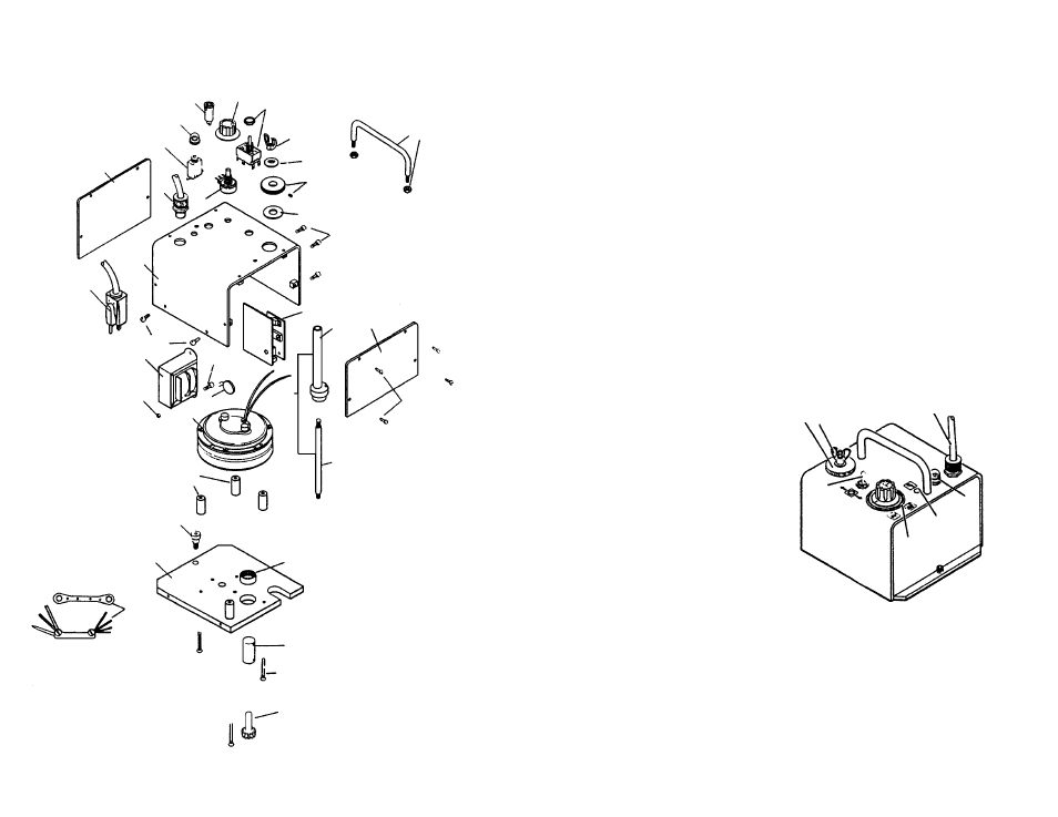
EXPLODED VIEW / BUG-5100-F DC III
DRIVE UNIT
11
14
12
13
29
36
28
15 17
10
18
16
21
24
23
35
6
5
4
3
2
7
8
9
20
25
22
19
31
27
26
32
30
33
34
1