Installation diagram, Installation cont – Caple Di454 User Manual
Page 7
.12.
GB
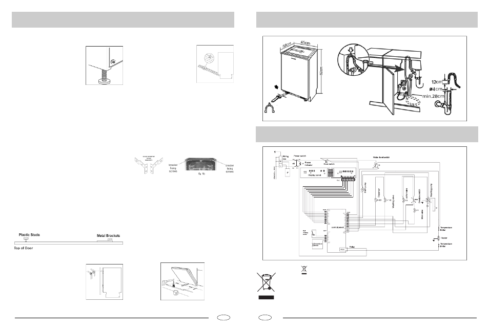
Installation
Diagram
.11.
GB
Supplied with the appliance is a plastic (self
adhesive) anticondensation strip, this
should be fixed to the underside of your
worktop along the front edge. The adjust-
able feet of the appliance allow it to be
raised up to 870mm, if the space between
the floor and the underside of the work
surface is greater than 870mm, then the
Stage 1
Installation cont..
To prevent damage to the floor covering, the appliance must be
installed using the plastic skids provided.
Stage 2
Connect the water, drain and electrical supplies (230 - 240V, 50Hz,
13A). We recommend that the appliance is connected to a cold
water supply.
Measure the width of the decor door.Align the template on the rear
of the door with the top of the door level with the top of the template,
and the left hand edge of the door in line with the measured door
width. Mark the four fixing poisitions. Repeat on the right hand side.
Remove the template, and drill pilot holes in the door in all eight
positions using a suitable drill (take care not to drill through the
door). Attach the upper plastic studs and lower fixing brackets to
the decor door as shown below.
Stage 3
Position the decor door onto the front of
the dishwasher by locating the brackets
into the two plastic studs mounted either
side on the top of the door. Lift the decor
door until the lower brackets locate into
the slots in the appliance door.
Stage 4
appliance should be positioned on suitable wooden spacers which
should always be fixed to the floor. Always use a spirit level to
make sure that the appliance is level left to right and front to back.
(If the appliance is installed on a carpet, ensure there is clearance
beneath the appliance). The four adjustable feet should be adjusted
to the correct height; the rear feet are adjustable via studs at the
front of the appliance (fig 1a).
fig 1a
Align the top of the decor door with
adjacent cabinets. Gently open door
whilst supporting the decor door.
Once in the lowered position, secure
the decor door using the fixing
screws provided as shown in the
diagram. Cover the screw heads
using the plastic caps provided.
Stage 5
The dishwasher should now be screwed to the underside of
the worktop, via the two fixing holes in the top trim.
For non-wooden worktops (e.g. marble) two brackets are
provided to allow the appliance to be secured to the sides of
the adjacent cabinets. The should be secured to the appli-
ance using the two screws at the top of the chassis (see fig
1b), adjusted to the correct width and then screwed to the
adjacent sides panels using suitable screws.
Stage 6
The door balance can be adusted via two screws accessed
through two holes in the top of the front frame. Adjust these
until the door just remains open under its own weight and is
level when open.
Stage 7
Cut clearance in the plinth to allow the door to open fully and
seal edges with a suitable varnish to prevent water ingress.
Stage 8
The symbol on the product or on its packaging indicates that this product may not be treated as household waste.
Instead it shall be handed over to the applicable collection point for the recycling of electrical and electronic equipment.
By ensuring this product is disposed of correctly, you will help prevent potential negative consequences for the environ-
ment and human health, which could otherwise be caused by inappropriate waste handling of this product.
For more detailed information about recycling of this product, please contact your local city office, your household waste
disposal service or the shop where you purchased the product.