Connecting multiple le-1s, Interconnecting le-1 and be-1 remote input modules, Dc power – Cloud Electronics LE-1MB User Manual
Page 4: Le-1 series installation guide v2.0 4, Cloud electronics limited, Cloud electronics usa
LE-1 Series Installation Guide v2.0
4
Connecting Multiple LE-1s
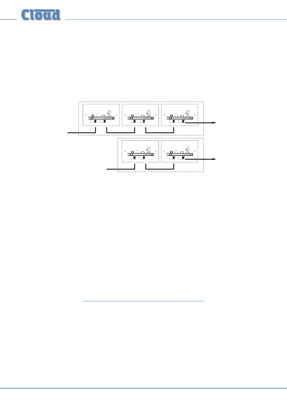
Multiple LE-1s may be “daisy-chained” together to provide input points at different locations in the same zone. Signals applied to
modules wired in this way will be summed together and fed to the DCM1 Line Input to which the “first” LE-1 in the chain (that
whose OUTPUT socket is connected directly to the DCM1). An internal gating circuit on each module automatically “disconnects”
any chained modules which are not in use, to minimise noise contribution. Chained modules will be treated as a single line input
at the DCM1.
Multiple LE-1s in the same zone may be daisy-chained by connecting the LINK RJ45 socket on the first LE-1 to the OUTPUT socket
on the second LE-1, and so on, as shown below.
LE-1
OUTPUT
LINK
LE-1
OUTPUT
LINK
LE-1
OUTPUT
LINK
LE-1
OUTPUT
LINK
LE-1
OUTPUT
LINK
To DCM1
Extension Ports
(one per zone).
ZONE 1
ZONE 2
Additional
input modules
Additional
input modules
Interconnecting LE-1 and BE-1 remote input modules
The Cloud BE-1 is an alternative range of optional remote line input modules, and provide a balanced stereo line input on XLR
connectors. LE-1 modules may be intermixed with BE-1s in a daisy-chain wiring arrangement in the manner described for LE-1s
alone, using the BE-1’s OUTPUT and LINK connectors. All the modules on a chain will be treated as a single line input at the DCM1.
Note that is not possible to intermix LE-1s with Cloud ME-1 remote microphone input modules in this manner.
DC Power
The LE-1 is powered from the DCM1’s EXTENSION PORTs via the Cat 5 connection. The LE-1 consumes 22 mA of current from
the DCM1 power supply.
If there is any doubt regarding the DCM1’s spare DC power capacity (as might be the case in a very large system with many CDR-1
remote controls, level restoration relays, etc.), please refer to the DCM1 Installation and User Guide (Appendix; PSU capacity) where
full details of the DCM1’s PSU ratings can be found.
Should you have any questions concerning the installation and connection of the LE-1, please visit ,
where you will find additional technical information.
Cloud Electronics Limited
140 Staniforth Road, Sheffield, S9 3HF. England.
Telephone: +44 (0)114 244 7051 Fax: +44 (0)114 242
5462 Web: www.cloud.co.uk E-mail: [email protected]
Cloud Electronics USA
2065 Sidewinder Drive, Suite 200, Park City,
Utah 84060. United States of America.
Toll Free: 0855 810 0161
Web: www.cloudusa.pro E-mail: [email protected]