5installing the lm-1 – Cloud Electronics LM-1 User Manual
Page 4
LM-1: Installation & User Guide
3
5
Installing the LM-1
5a
Hardware and Wiring Requirements
The Cloud LM-1 active panel is the same physical size as a double UK electrical socket (13A
Type) and can be mounted in the recessed back box provided or be surface mounted in a
standard 35mm deep housing. The LM-1 should be connected to the facility input of the host
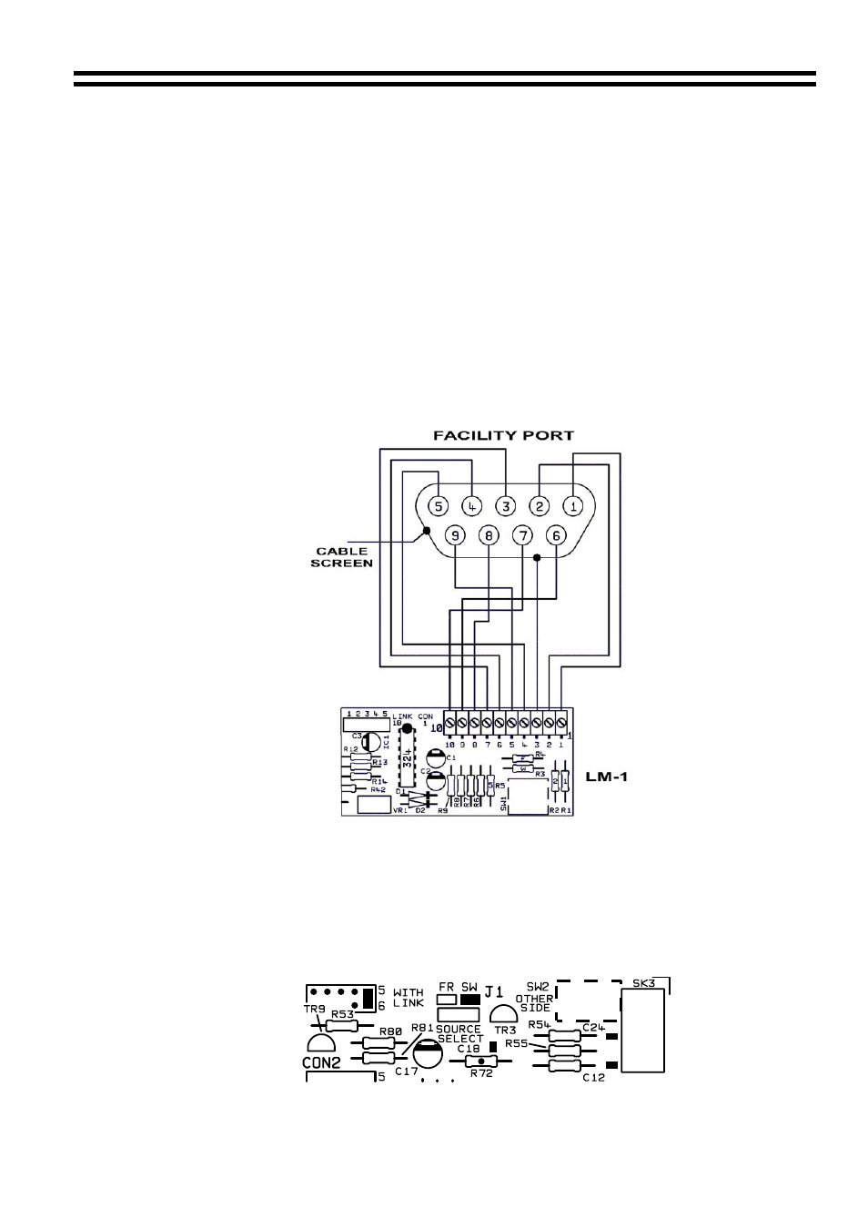
mixer or amplifier using 9-Core cable with an overall screen. The LM-1 terminations are
conventional screw terminals while the facility input on the host unit is a 9-Pin sub-D type
connector (D-Type is supplied with the LM-1). It is advised that you are vigilant when wiring
the LM-1 as wiring conventions between old and new host units do vary. Since the LM-1
derives its power from the host unit, certain wiring errors can cause power supply problems,
resulting in temporary shutdown of the host mixer. If a problem such as this is experienced,
disconnect the facility connector and double check the wiring against the diagram. The mixer
should be switched off for approximately 30 seconds after the initial failure to allow it to reset.
Note that we recommend a cable length of no more than 100m (328ft).
5b
Connecting the LM-1 to a 46/50, Z4
II
or Z8
II
5c
Configuring the Z4
II
or Z8
II
to the LM-1
When an LM-1 is connected to a zone please ensure that the music control switch is
depressed. If the LM-1 fails to change the music sources, check that jumper J1 is in the
‘SW’ position.
Location of Jumper J1
04-11-02 V4.0