Vca-2 installation guide, 1 introduction, 2 installation information – Cloud Electronics VCA-2 User Manual
Page 2: 3 installation instructions
VCA-2: Installation Guide
1
VCA-2
Installation Guide
1 Introduction
The VCA-2 is an optional module that fits inside the CX-A4 or CX-
A6 and provides two channels (1&2 or 3&4 etc) with the facility to
have remote control of the level (using the RL-1 remote level
control). The CX-A4 can accommodate up to two VCA-2 modules
and the CX-A6 can accommodate up to 3 modules. The unit can
control two channels independently or provide stereo attenuation.
• For independent operation of the two channels the ‘solo/link’ switch should be depressed with
a remote level control (RL-1) wired to each 3 pin connector.
• For stereo operation, release the ‘solo/link’ switch and connect a remote level control to the
left connector only, as viewed form the rear of the amplifier.
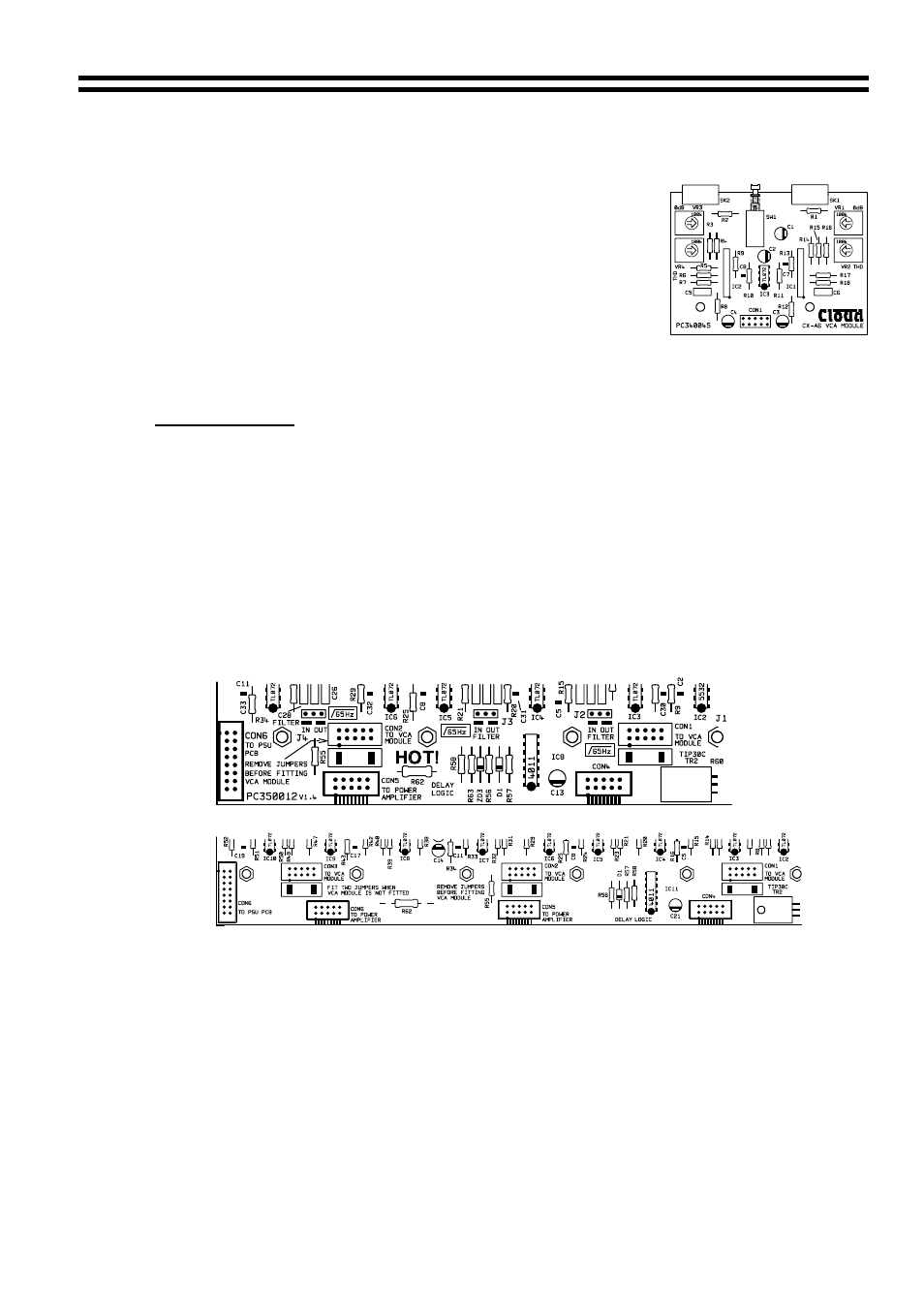
2 Installation
Information
The VCA-2 is supplied with two 40mm M3 hex spacers, one plastic insert & two 3-pin screw
terminal plugs. The connectors to install the VCA modules are to the rear of the amplifier
clearly marked on the PCB as ‘CON X TO VCA MODULE’ where ‘X’ is 1,2 or 3 see below: -
CON 1 = Channel 1&2
CON 2 = Channel 3&4
CON 3 = Channel 5&6 (only on CX-A6)
Note: A VCA-2 and Bose
equalisation module cannot be installed together on the same
channel.
CX-A4
CX-A6
3 Installation
Instructions
1. Turn the power off and remove mains cable.
2. Remove the top panel
3. Select the required PCB mounted VCA connector (see notes above) and remove both
jumpers from it.
4. Remove the relevant blanking plate from the rear panel and push the plastic plug into the
‘clip protect’ hole.
5. Two M3 fixing screws can be found on the motherboard adjacent to the VCA connector.
Remove & retain these screws then fix the 40mm M3 hex spacers in their place.
26-02-02 V2