Cloud Electronics VCA-2 User Manual
Page 3
Advertising
2
VCA-2: I
NSTALLATION
G
UIDE
26-02-02 V2
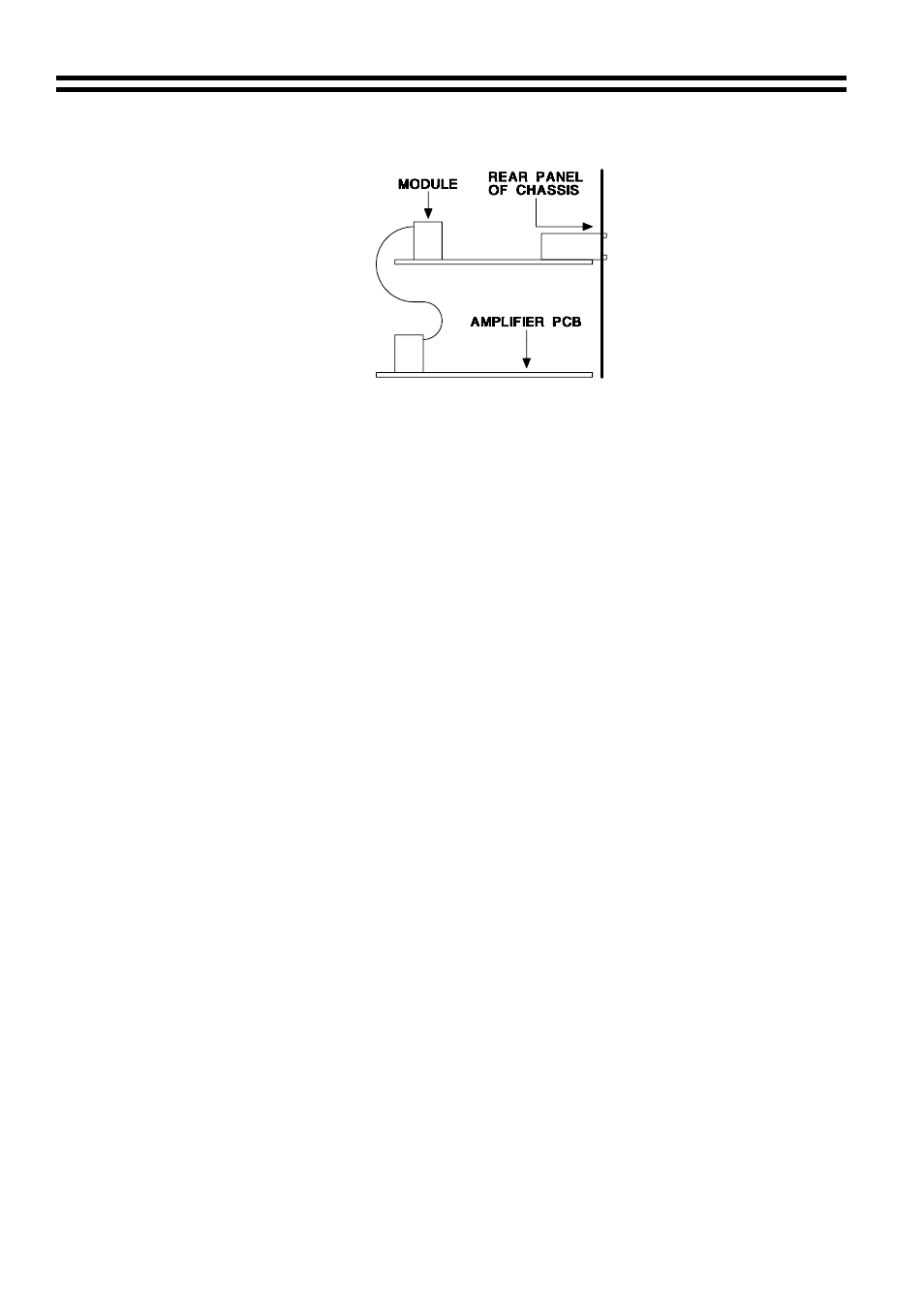
6. Push the 10-way plug onto this VCA connector aligning the plug so the cable approaches it
from the rear of the chassis (see diagram below), check the connector mates to all 10 pins.
7. Position the 3-pin sockets and switch of the VCA module through the cut-outs in the rear
panel and align the holes in the VCA module over the two 40mm spacers
8. Secure the VCA module to the 40mm spacers with two M3x6 screws (removed earlier)
9. Fit the top panel.
If you have any further questions please contact our technical staff
(contact details on front cover)
Bose
is a registered trademark of The Bose Corporation
Advertising