Installation & user guide, 1introduction, 2installation information – Cloud Electronics CXL-400 User Manual
Page 2: Cxl-400 installation & user guide, 1 introduction, 2 installation information, 3 signal requirements
CXL-400: Installation guide
1
CXL-400
Installation & User Guide
1 Introduction
The CXL-400 is a 100/70V-line module consisting of 4 transformers intended for use in high
quality background music and public address systems up to 40W rms. It can be installed
internally to the 44/50 and CX-A200.
2 Installation
Information
The CXL-400 is supplied with 10 M3
×6 screws an 8-way cable and 2 10mm M3 hex spacers.
The transformers are mounted on a PCB with M3 fixing bushes and screw terminal output
connectors. The CXL-400 is fitted inside the 44/50 and CX-A200.
70V/100V-line systems are
capable of delivering an electrical shock so must be wired with the appropriate level of care.
3 Signal
Requirements
The CXL-400 can be used at full power with frequencies down to 50Hz. If it is operated with
high level input signals at frequencies below 50Hz it may saturate and cause the driving
amplifier’s VI limiter to operate. Care must be taken to ensure that high level low frequency
input signals (50Hz and below) are removed from the signal when using a CXL-400.
4
44/50 Installation Instructions
1. Turn the power off and remove the mains cable
2. Remove top panel
3. Remove the mains socket and mains switch from the chassis leaving the wires connected
4.
Set the relevant transformers (see below) to 70V operation if required by moving the solder
link on the underside of the PCB from 100V to 70V, the factory default is 100V.
TX1 = Zone 1, TX2 = Zone 4, TX3 = Zone 3 & TX4 = Zone 4
5. Carefully place the CXL-400 board in the chassis alongside the power supply transformer
with the output connector protruding through the rectangular cut out in the rear of the chassis
and the transformers facing inside the chassis.
6. Secure the CXL-400 to the side of the chassis with the 8 provided M3
×6 screws.
7. Reinstall the mains switch and socket
8. Connect the CXL-400 to the main board using the 8-way cable (see note).
9. Replace the top panel and fit the protective cover over the outputs of the CXL-400 using the
two 10mm M3 hex spacers and remaining two screws
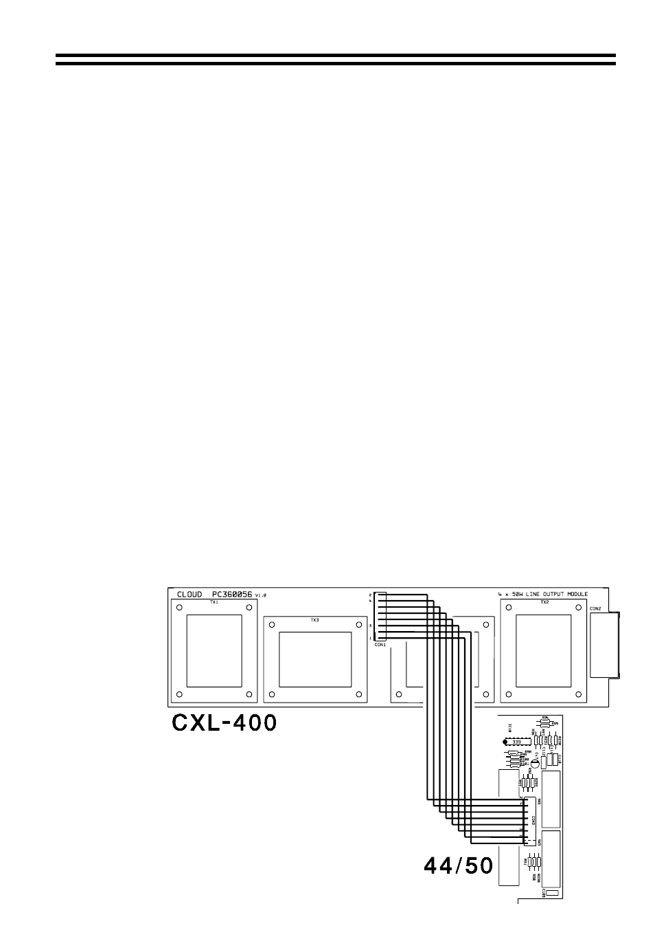
Wiring Between CXL-400 and 44/50
NOTE: If you wish
to disable a
transformer on
any zone simply
remove its
relevant wire, from
the 8-way
connector. The
zone numbers are
clearly marked
near the connector
on the CXL-400
and 44/50 PCB
(See diagram on
right).
16-07-02 V2