5cx-a200 installation instructions, 6output cable requirements – Cloud Electronics CXL-400 User Manual
Page 3
2
CXL-400: Installation guide
5
CX-A200 Installation Instructions
1) Turn the power off and remove the mains cable
2) Remove top panel
3) Remove spade terminals from the Mains Switch (taking note of the wiring) then remove the
switch from the front panel.
4) Set the relevant transformers (see below) to 70V operation if required by moving the solder
link on the underside of the PCB from 100V to 70V, the factory default is 100V.
TX1 = Channel 1, TX2 = Channel 2, TX3 = Channel 3 & TX4 = Channel 4
5) Carefully place the CXL-400 board in the chassis alongside the power supply transformer
with the output connector protruding through the rectangular cutout in the rear of the chassis
and the transformers facing inside the chassis.
6) Secure the CXL-400 to the side of the chassis with the 8 M3
×6 screws.
7) Rewire the mains switch
8) Connect the CXL-400 to the main board with the 8-way cable (see note).
9) Replace top panel and fit the protective cover over the outputs of the CXL-400 using the two
10mm M3 hex spacers and remaining two screws
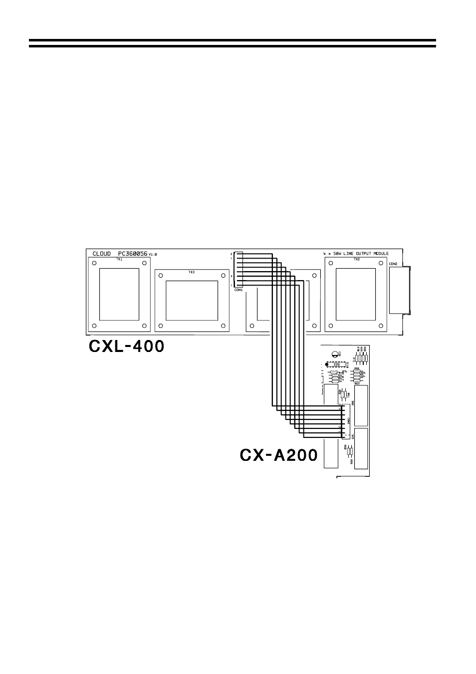
Wiring Between CXL-400 and CX-A200
*NOTE: Should you wish to disable a transformer on any channel simply remove the relevant
wire, from the 8-way connector. The channel numbers are clearly marked near the 8-way
connector on both the CXL-400 and CX-A200 PCB.
6
Output Cable Requirements
The cable used for the 70V/100V-line output must be 0.75mm
2
or more, double insulated and
capable of carrying at least 1A rms. With long distances, it may be advantageous to use thicker
cable. The CXL-3120 transformers are not of the auto transformer type and hence provide a
fully balanced output signal which is isolated from the amplifier.
11-01-02 V1