Phantom power, Dc power, Me-1 installation guide v1.0 4 – Cloud Electronics ME-1 Installation User Manual
Page 4
ME-1 Installation Guide v1.0
4
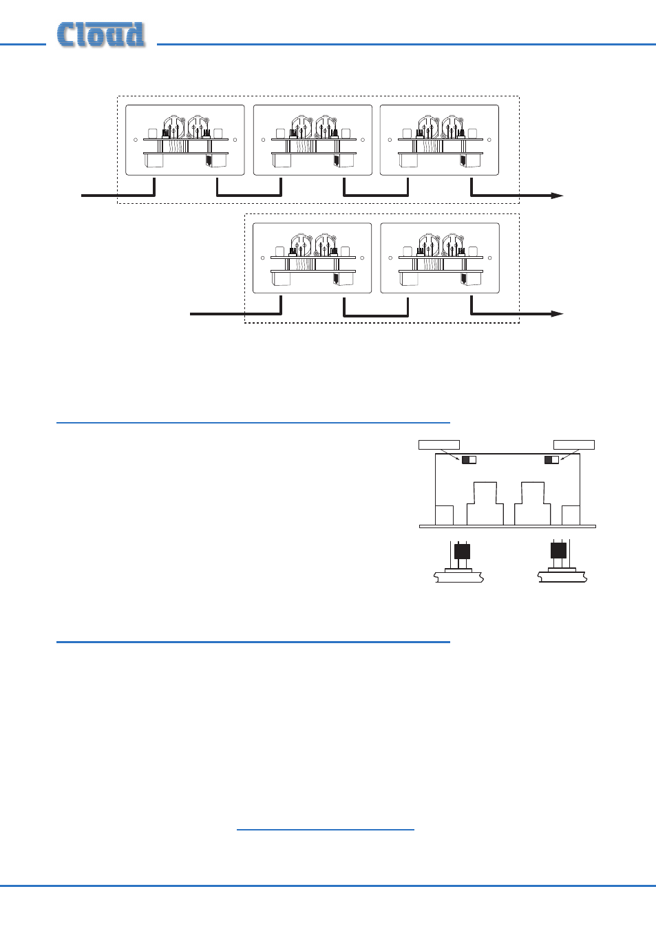
To DCM-1
Microphone Inputs
(one per zone).
ZONE 1
ZONE 2
Additional
input plates
Additional
input plates
ME-1
OUTPUT
LINK
ME-1
OUTPUT
LINK
ME-1
OUTPUT
LINK
ME-1
OUTPUT
LINK
ME-1
OUTPUT
LINK
Note that it is not possible to intermix ME-1s with either Cloud LE-1 or BE-1 remote
line input plates in this manner.
Phantom Power
12 volt phantom power may be enabled on either input
channel. The installer should determine what type of
microphone(s) are to be used with the ME-1 before
setting these, as inadvertently-applied phantom power
can damage some types of dynamic microphone.
Phantom power is enabled by moving the two jumpers
on the rear pcb, as shown.
DC Power
The ME-1 is powered from the DCM-1’s MICROPHONE INPUTs via the CAT-5
connection. The ME-1 consumes 43mA of current at both +12v and -12v from the
DCM-1 power supply.
If there is any doubt regarding the DCM-1’s spare DC power capacity (as might be the
case in a very large system with many CDR-1 remote controls, level restoration relays,
etc.), please refer to page 53 of the DCM-1 Installation and User Guide where full
details of the DCM-1’s PSU ratings can be found.
Should you have any questions concerning the installation and connection of the
ME-1, please contact our Technical Support staff (details on front cover).
(REAR VIEWS)
Phantom power OFF
Phantom power ON
(TOP VIEW)
Channel 1
Channel 2
(REAR VIEWS)
Phantom power OFF
Phantom power ON
(TOP VIEW)
Channel 1
Channel 2
(REAR VIEWS)
Phantom power OFF
Phantom power ON
(TOP VIEW)
Channel 1
Channel 2
(REAR VIEWS)
Phantom power OFF
Phantom power ON
(TOP VIEW)
Channel 1
Channel 2