Subrack, Power input – Codan Radio MT-3 User Manual
Page 38
USER GUIDE | MT-3 ANALOG RADIO SYSTEMS
Chapter 5: Radio System Components
Page 30
SUBRACK
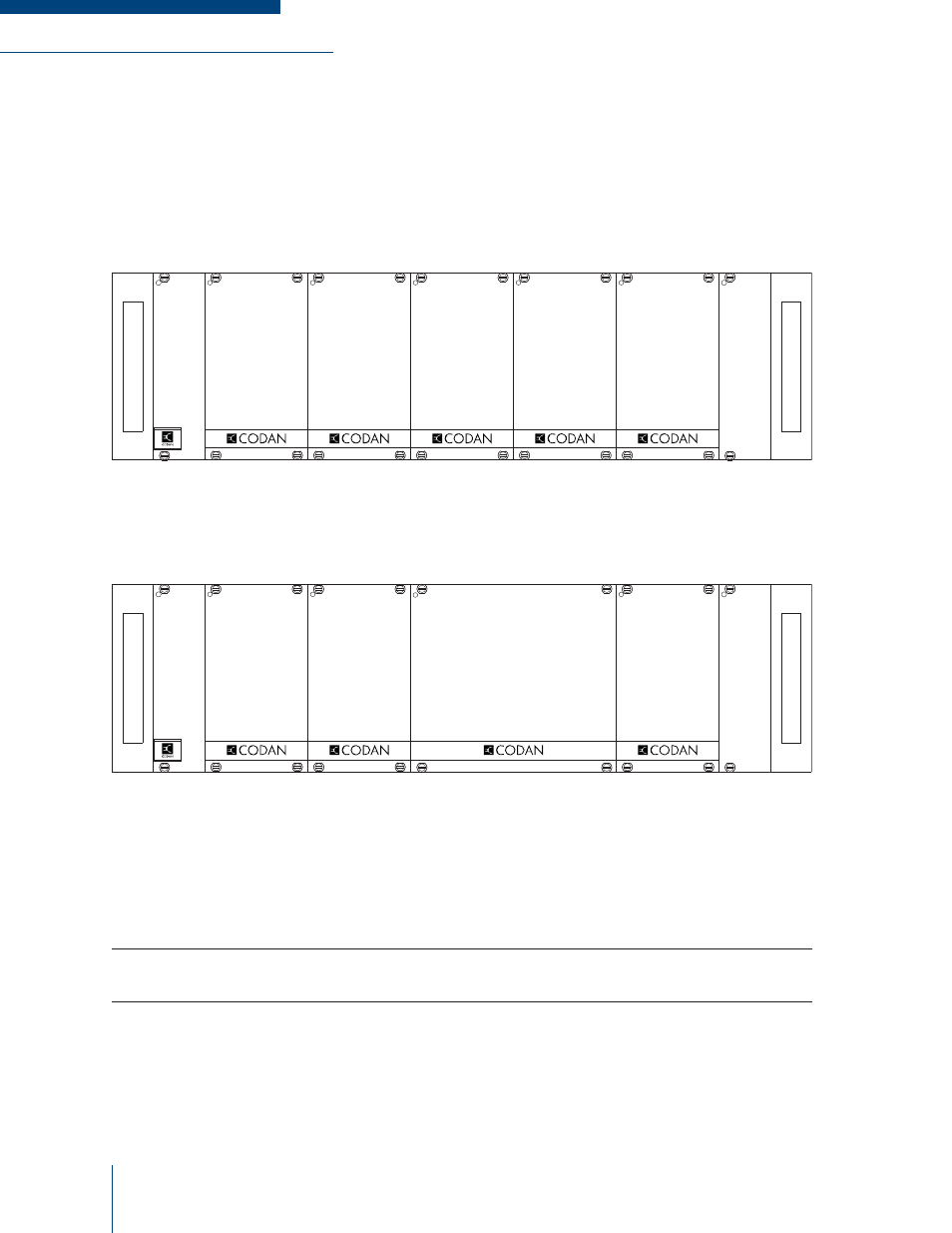
The SR-39-1 subrack is designed to hold and interconnect the MT-3 series of receiver, transmitter and
control modules on one universal motherboard. The subrack has room for two receiver and transmitter
pairs. The left side connectors are reserved for transmitter A and receiver A, while the right side
connectors are reserved for transmitter B and receiver B. See Figure 5-1.
Figure 5-1: Standard Subrack Confi guration
If a VHF or UHF 30 Watt power amplifi er is installed, only one transmitter and receiver pair can be
installed. The power amplifi er takes up two slots as shown in Figure 5-2.
Figure 5-2: Standard Subrack with Power Amplifi er
Power Input
The main power input (+10 to +17 Vdc; +13.8 Vdc nominal) connector is located at the back of the
subrack, on the motherboard. There is an identical +9.5 Vdc power output connector on the motherboard
that is used to power other Codan equipment at +9.5 Vdc.
NOTE: Do not connect the main power input to the +9.5 Vdc power output connector, as a transient
suppressor (over voltage protection) will short to ground to protect the equipment.
Reverse voltage protection and over voltage protection (transient suppressor) is provided at the main
power input as well as the +9.5 Vdc line. The main power input is protected with a standard fast-blow
15 amp fuse. These components may require replacing if the power supply is not connected properly,
or even after a power surge or a lightning strike. The two transient suppressors have different voltage
ratings for the main power input and +9.5 Vdc lines. Figure 5-3 shows the subrack / motherboard rear
view.
SYSTEM
REGULATOR
RECEIVER
B
TRANSMITTER
B
RECEIVER
A
TRANSMITTER
A
CONTROL
CARD
POWER AMPLIFIER
A
SYSTEM
REGULATOR
RECEIVER
A
TRANSMITTER
A
CONTROL
CARD