Code CR2600 Charging Station User Manual
Code Hardware
Place the Charging Station on top of the weighted base (Figure 1) and secure the
Charging Station to the base with the screws provided (Figure 4)
Weighted Base Adapter Plate
The weighted base has the same pre-drilled mounting holes as the ECS-H and UMC
Chargers.
14870 S. Pony Express Rd., #200 Bluffdale, UT 84065
www.codecorp.com (801) 495-2200
14870 S. Pony Express Rd., #200 Bluffdale, UT 84065
www.codecorp.com (801) 495-2200
Figure 5
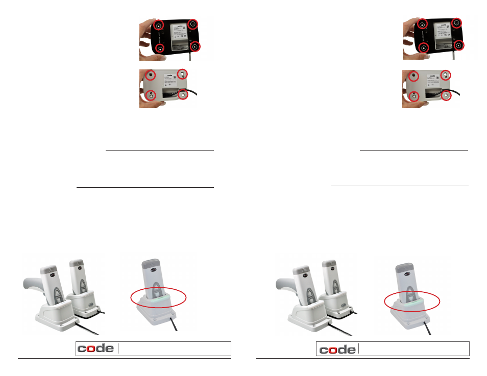
Charging a CR2600
Batteries ship with approximately 50% battery life and should be completely charged
before initial use. Approximate time to charge a depleted battery is 4 hours via USB
cable and 2-3 hours via AC power supply.
To charge a reader, place either a palm or handled CR2600 into the charging bay (Figure
7). When the reader is seated correctly, the Charging Indicator LED (Figure 8) will turn
green.
Figure 7
Figure 8
3. Rubber feet can be placed on the corners of the
weighted base (Figure 5) or directly onto the
Charging Station (Figure 6) to prevent slipping
from a surface.
4. (Optional) Mounting the Charging Station to
a Surface. Place the ‘This Side Down’ (Figure
3) side of the weighted base onto the surface,
and secure with screws. Note: Because surface
types differ, screws are not included to mount a
Charging Station to a surface.
Figure 5
Place the Charging Station on top of the weighted base (Figure 1) and secure the
Charging Station to the base with the screws provided (Figure 4)
Weighted Base Adapter Plate
The weighted base has the same pre-drilled mounting holes as the ECS-H and UMC
Chargers.
Charging a CR2600
Batteries ship with approximately 50% battery life and should be completely charged
before initial use. Approximate time to charge a depleted battery is 4 hours via USB
cable and 2-3 hours via AC power supply.
To charge a reader, place either a palm or handled CR2600 into the charging bay (Figure
7). When the reader is seated correctly, the Charging Indicator LED (Figure 8) will turn
green.
Figure 7
Figure 6
Figure 8
3. Rubber feet can be placed on the corners of the
weighted base (Figure 5) or directly onto the
Charging Station (Figure 6) to prevent slipping
from a surface.
4. (Optional) Mounting the Charging Station to
a Surface. Place the ‘This Side Down’ (Figure
3) side of the weighted base onto the surface,
and secure with screws. Note: Because surface
types differ, screws are not included to mount a
Charging Station to a surface.
Figure 6